
How to Plan a Municipal Streetlight Pilot Project: Evaluation Guide
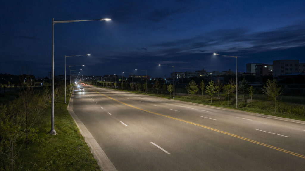
Learn how to plan a municipal streetlight pilot project using baseline data, lighting evaluation, controls testing, energy measurement, and resident feedback
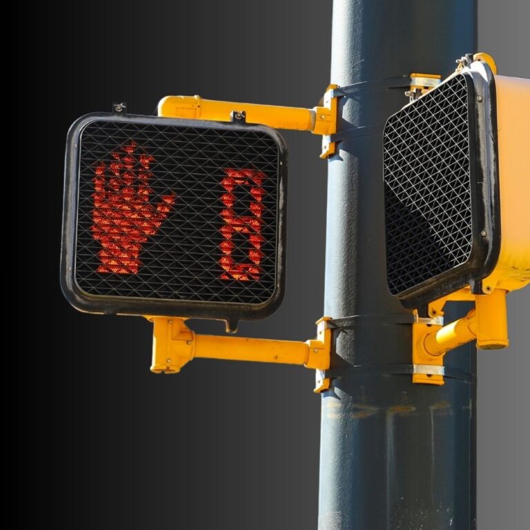
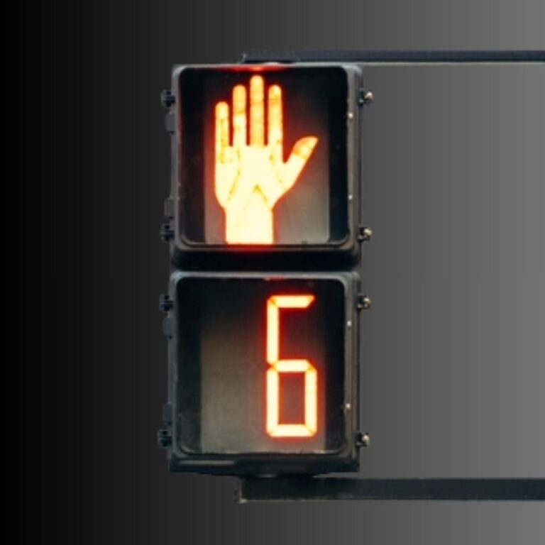
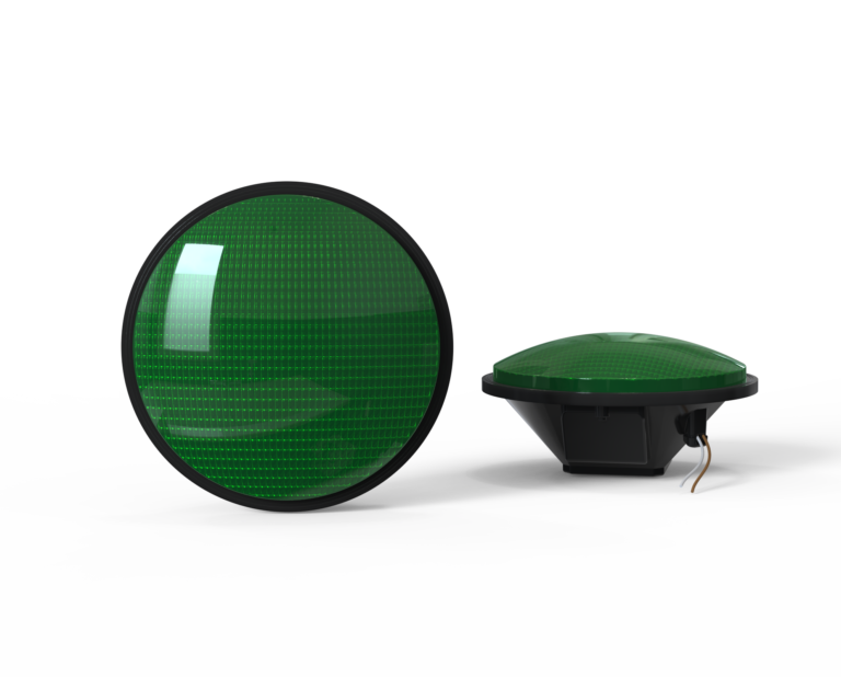
Countdown Signal Module
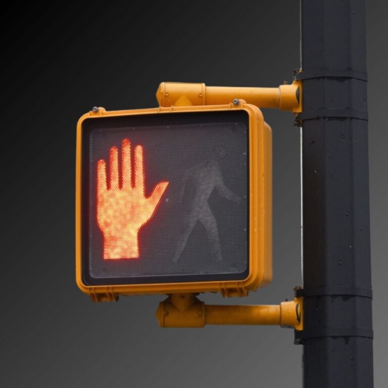
Hand & Person Overlap
Hand & Person Side by Side
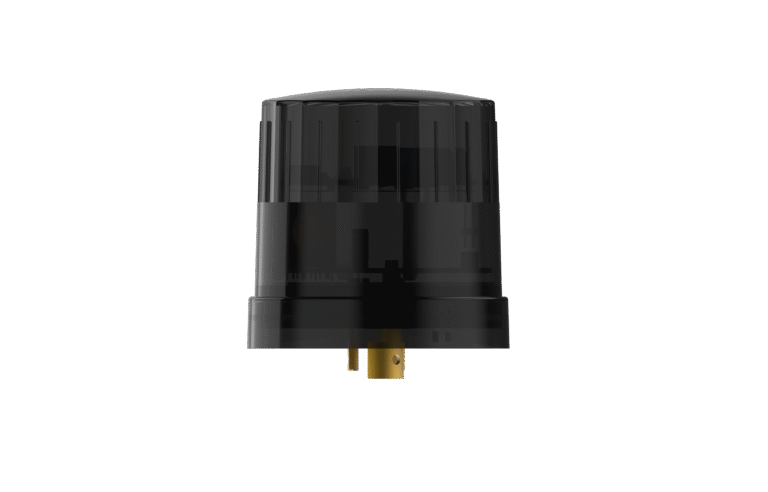
External / Plug-and-Play Smart Node (Mounts externally to the fixture)
Integrable lighting products
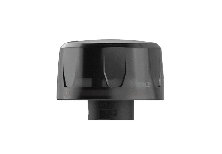
Internal / Integrated Smart Node (Built directly inside the luminaire)
Integrable lighting products
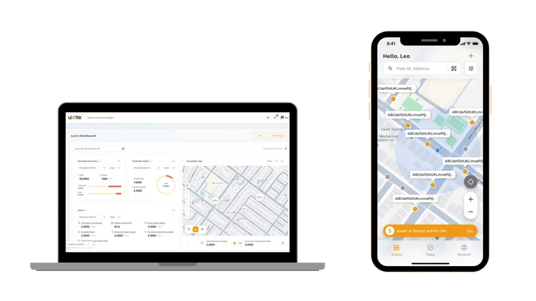
The central AI management system (CMS) of the LEOlink Intelligent Lighting System.
Integrable lighting products
Frontier isn’t just a name—it’s a declaration. Born from the legacy of Dialight’s trusted traffic signal designs and reimagined by LEOTEK’s innovation-driven R&D and product management teams, Frontier stands as a symbol of reliability, evolution, and regional adaptation.

Learn how to plan a municipal streetlight pilot project using baseline data, lighting evaluation, controls testing, energy measurement, and resident feedback

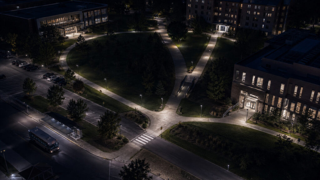
Campus pathway lighting should be planned around the routes people use after dark, not selected as a stand-alone fixture exercise. A useful plan connects route hierarchy, visual tasks, wayfinding, accessible-route context, glare and spill control, controls, project-specific photometry, and documentation review.

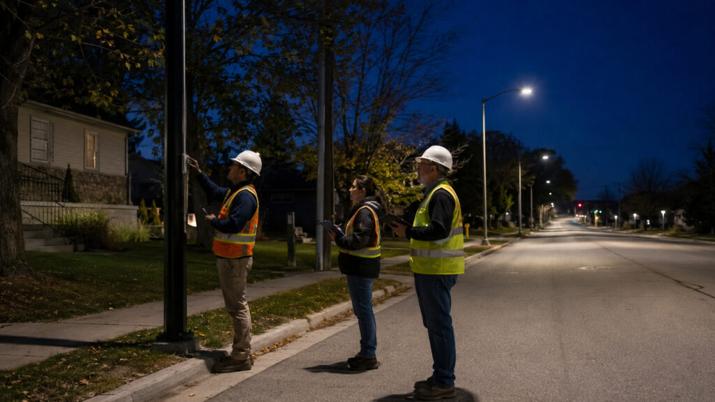
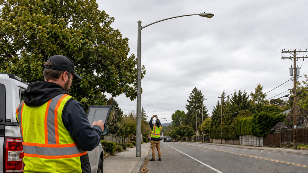
A municipal streetlight audit is a reconciled record of each light, who owns it, how it is billed and maintained, and what field conditions could affect a conversion. Before selecting LED equipment, a city or agency should compare its records with field observations and document what is verified, uncertain, or in need of qualified review.

Ambient temperature affects an LED streetlight by changing how readily the luminaire can release internally generated heat. Hot conditions can raise LED and driver operating temperatures, accelerating lumen depreciation and stressing components, while cold conditions generally favor LED thermal performance but still require verified low-temperature and cold-start ratings.

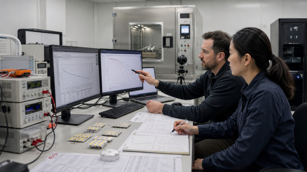
LM-80 measures luminous-flux and color maintenance for LED packages, arrays, or modules under stated test conditions; TM-21 projects longer-term luminous-flux maintenance from applicable source data. For a streetlight claim based on LM-80 and TM-21, neither method alone proves how long the complete luminaire will operate without failure.

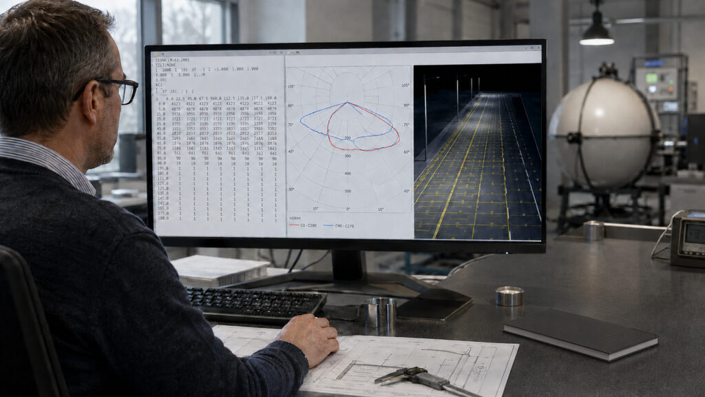
A reliable IES file interpretation starts by verifying the luminaire and test identity, decoding the vertical and horizontal angle lists, and matching each candela series to its measurement plane. After that, compare the raw data with the polar plots and the project-specific roadway model rather than accepting a rendering as the whole analysis.

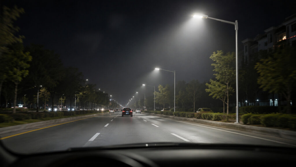
Veiling luminance describes the contrast-reducing luminous veil caused by stray light in the eye, while threshold increment expresses how much more contrast is needed to see a target when glare is present. Together, veiling luminance and threshold increment help engineers evaluate roadway disability glare, but the results are meaningful only when the governing method and its assumptions are identified.

Learn how to calculate roadway lighting uniformity ratios, compare average and minimum illuminance, and properly review streetlight photometric plans.

A floodlighting beam angle is only one input: start with the task area, then test the actual luminaire photometry against mounting height, setback, and aiming direction. Beam angle alone cannot confirm coverage, glare control, structural suitability, or compliance with a local requirement.

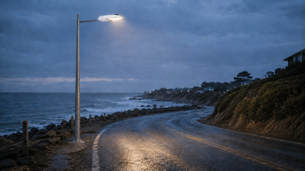
Coastal streetlight corrosion is best managed as an installed-assembly and maintenance decision, not as a single material label or salt-fog hour count. For a roadway luminaire near salt water, agencies should evaluate the local exposure, housing and finish, fasteners and interfaces, seals and drainage, documentation, and the plan for inspection and repair.