TOP BAR

VersaTEK

Compare VersaTEK LED lighting models for flood, site and area, and off-roadway applications. Review sizes, mounting options and product specifications.

Explore related applications: Outdoor lighting applications · All Outdoor Lighting products

VersaTEK Large Floodlight
VersaTEK
Lumen Output: 23,938–59,962 lm (70 CRI)
Voltage: 120–277V / 347–480V
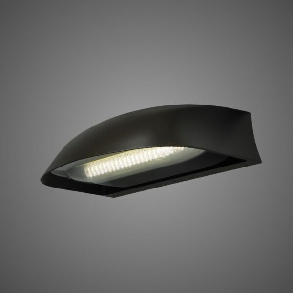
LEOTEK VTLOR off-roadway LED luminaire lit from below, showing the optical face and closed housing
VersaTEK
Lumen Output: 27,606–65,674 lm (70 CRI)
Voltage: 120–277V / 347–480V
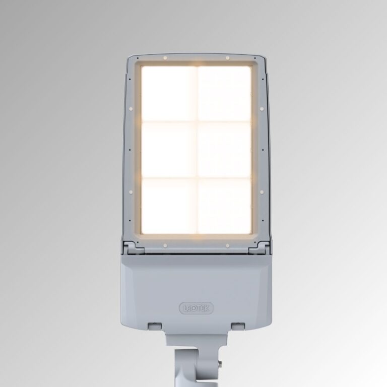
VersaTEK Large Site & Area – VTLSA
VersaTEK
Lumen Output: 27,606–65,674 lm (70 CRI)
Voltage: 120–277V / 347–480V
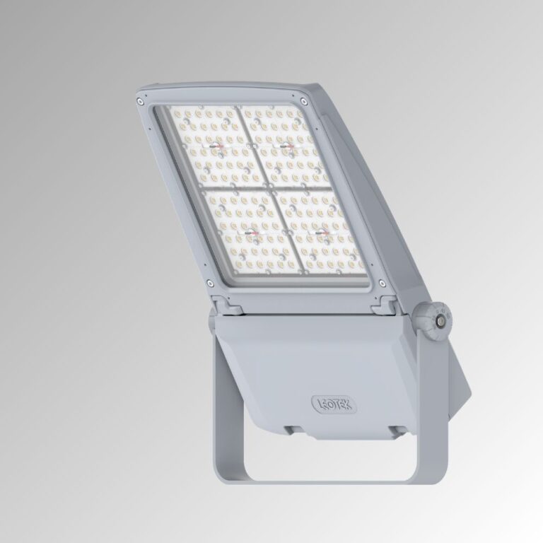
VTMFL-YK ISO View 60 Degree
VersaTEK
Lumen Output: 8,399–42,305 lm (70 CRI)
Voltage: 120–277V / 347–480V
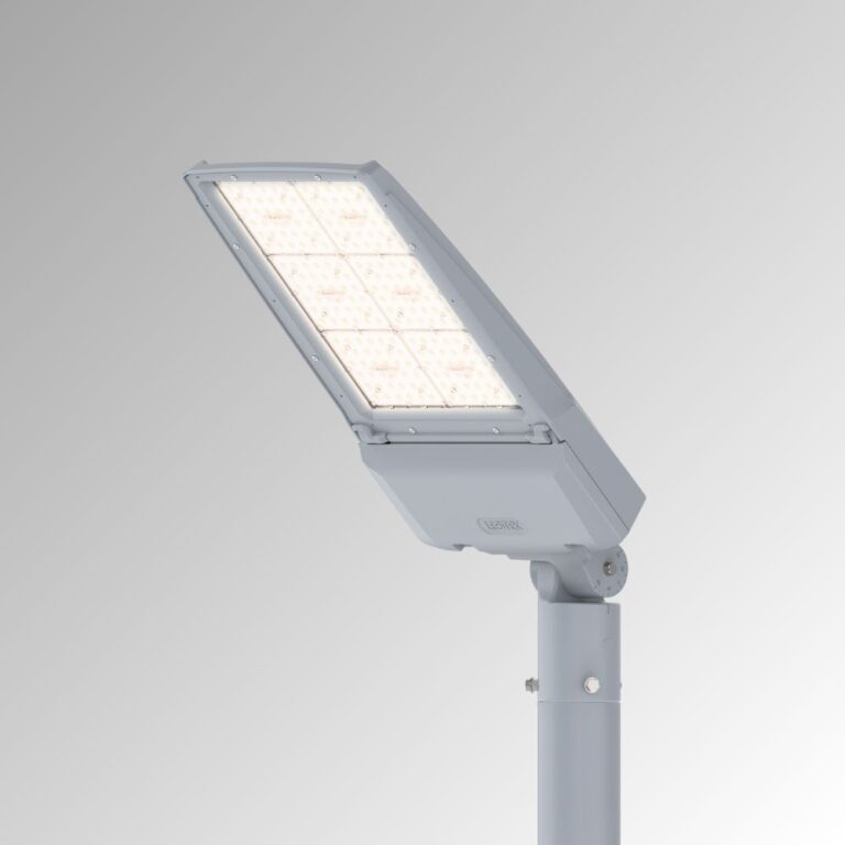
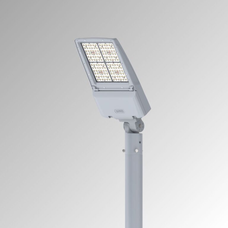
VTMOR-SF ISO View 60 Degree Tall Pole (Temp Version)
VersaTEK
Lumen Output: 8,878–51,526 lm (70 CRI)
Voltage: 120–277V / 347–480V
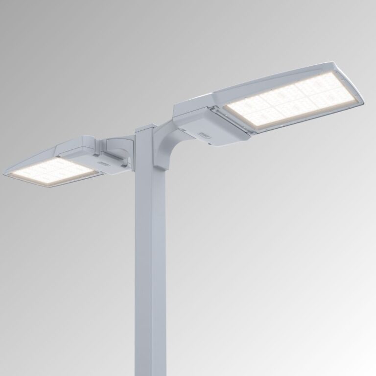
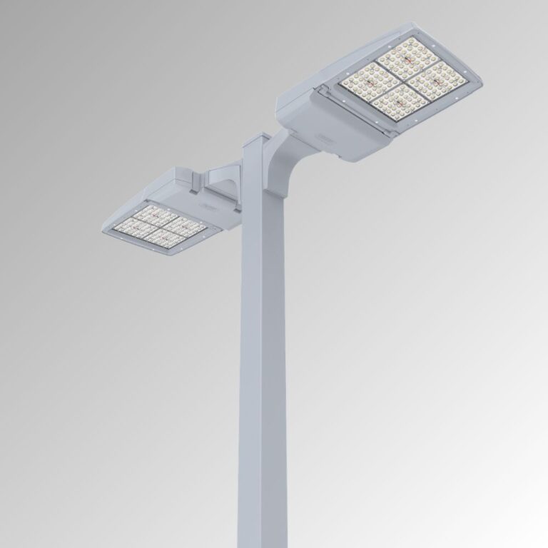
VTMOR SA-SPM Twin Tall Pole ISO View LEDs
VersaTEK
Lumen Output: 8,878–51,526 lm (70 CRI)
Voltage: 120–277V / 347–480V
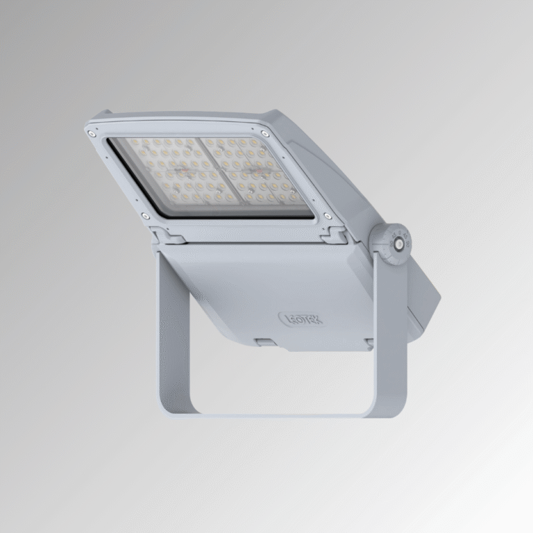
VersaTEK VTSFL LED array supported by a U-shaped bracket.
VersaTEK
Lumen Output: 4,357–26,040 lm (70 CRI)
Voltage: 120–277V / 347–480V
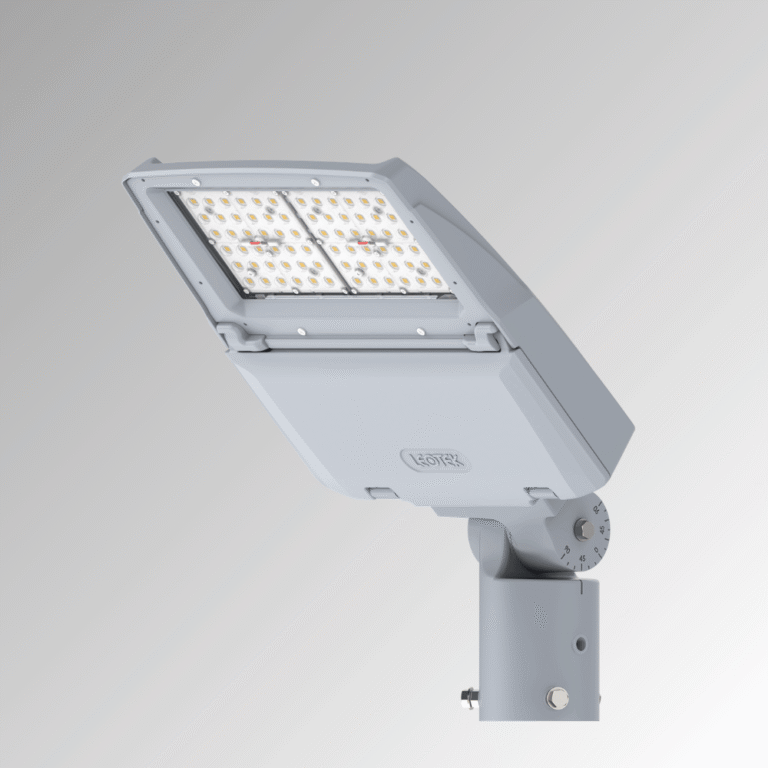
VersaTEK VTSOR LED array on an adjustable mount.
VersaTEK
Lumen Output: 4,577–28,325 lm (70 CRI)
Voltage: 120–277V / 347–480V
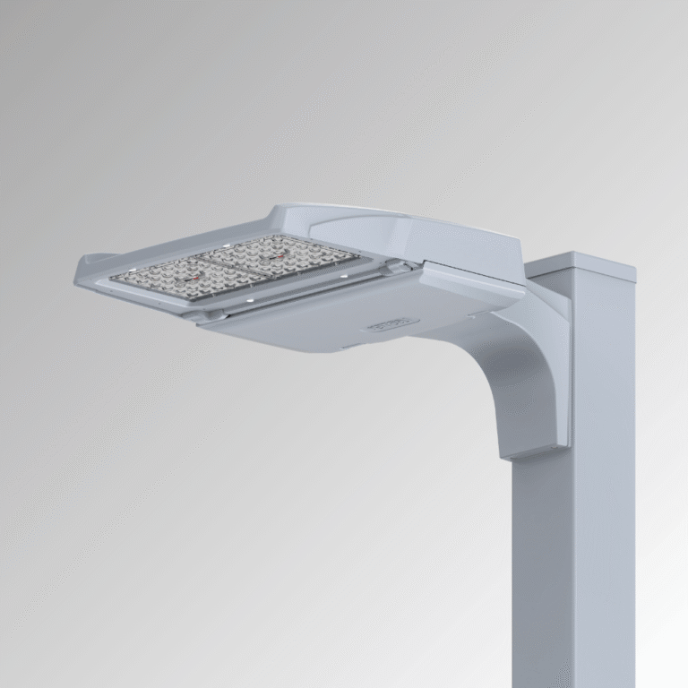
VersaTEK VTSSA on a horizontal mounting bracket.
VersaTEK
Lumen Output: 4,577–28,325 lm (70 CRI)
Voltage: 120–277V / 347–480V
About Us

Why LEOTEK?

Building a Safer, Greener, and Smarter City with AIoT

LEOLab

Lighting & Smart City Solutions

Check our LEOLab pages to find more information.

Contact Us

Need Product Support & Inquiry?

If you need any service, please feel free to contact us!

PROJECT SUPPORT

VersaTEK FAQs

Answers to common questions about product selection, installation and procurement.

What do OR, SA and FL designate?

OR is the OFF-Roadway family, SA the Site & Area family, and FL the Floodlight family, each offered in small/medium/large platforms. Select the application family before sizing because mounting and optical choices differ. For example, VTSSA offers site-area pole and wall mounts, whereas a floodlight selection must define aiming and beam coverage. The similar housing platform does not make every family’s mounting or optics interchangeable.

Specifications & documents
VersaTEK® Small OFF-Roadway Series – VTSOR · VersaTEK® Small Site & Area Series – VTSSA · VersaTEK® Small Floodlight Series – VTSFL

Further reading
Floodlighting Beam Angle: Selection and Aiming

How should I choose small, medium or large fixtures?

Choose by the required photometry and allowed loading, then verify the model’s performance table. VTSSA’s published 70 CRI range is 4,577–28,325 lm at 30–165W across configurations. A large fixture is not automatically required for a large site: pole placement, mounting height, optic and aiming all affect usable coverage. Use the exact size/application/CCT/CRI/performance code in the IES calculation and fixture schedule.

Specifications & documents
VTSSA Spec Sheet

Further reading
How to Read an IES File · Roadway Lighting Uniformity Ratios

Can a Site & Area model also be treated as an aimed floodlight?

Use the mounting and optics documented for the selected family. VTSSA offers fixed/adjustable pole-arm, mast-arm fitter and wall-mount configurations, with specific permitted combinations. Floodlight models are separate catalog entries with their own beam and aiming data. If one site needs both area illumination and aimed floodlighting, show separate line items and IES calculations rather than approving one generic VersaTEK configuration for both.

Specifications & documents
VTSSA Spec Sheet · VersaTEK® Small Floodlight Series – VTSFL

Further reading
Floodlighting Beam Angle: Selection and Aiming

How should aiming and glare be controlled?

Record mount position, aiming angle, rotation, target area and nearby roads/properties in the lighting calculation and installation plan. Use the selected model’s optics and permitted shields; current VTSSA lists shield compatibility by optical configuration. After installation, check orientation against the approved layout. An installer’s field tilt change can alter both target coverage and high-angle light, even when the fixture wattage remains unchanged.

Specifications & documents
VTSSA Spec Sheet

Further reading
Floodlighting Beam Angle: Selection and Aiming

What matters when using an existing pole or wall?

Check the exact mounting code, pole/structure condition, attachment dimensions, fixture weight and EPA for the chosen configuration. VTSSA lists different weights by mount and provides separate pole/wall arrangements. Its tool-free electrical access and VersaKICK door support assist service, while PWRD is an optional removable power door. Include maintenance access in the location review instead of assuming every housing/mount has the same loading or service clearance.

Specifications & documents
VTSSA Spec Sheet

Further reading
Streetlight EPA: Wind Load and Pole Design

Can a warmer CCT or an 80 CRI option be selected without recalculating output?

No. Current VTSSA offers 2700K/3000K/4000K/5000K, with 80 CRI choices at 3000K/4000K/5000K. The sheet provides a multiplier for the 80 CRI option; nominal photometry also varies with optic and performance code. Use the selected configuration’s IES or approved scaling for the calculation. A CCT/CRI change made for appearance should not retain an unadjusted output claim from a different configuration.

Specifications & documents
VTSSA Spec Sheet

Further reading
How to Read an IES File

Which controls cannot simply be combined?

VTSSA NB01-Plus requires PCR7CR and the standard 0–10V driver; NB01-Plus and the PS selector are not compatible with the D4I driver choice. D4i/TLR receptacles are a separate DALI control route. MSL3P/MSL7P uses a photocontrol receptacle with pins 6/7 unwired and is not compatible with wireless nodes. Check mounting and sensor restrictions before ordering so the control schedule describes a valid combination.

Specifications & documents
VTSSA Spec Sheet

Further reading
Streetlight CMS Architecture: Nodes, Networks and Central Management

What surge and warranty distinctions affect lifecycle cost?

For current VTSSA, standard SP1 is 10kV/5kA fail-to-on; SP2 is 20kV/10kA fail-to-on, while LSSP2 is 20kV/10kA fail-to-off. These failure modes have different operating implications. The sheet lists ten-year standard luminaire coverage and shorter coverage for motion-sensor configurations. Include the selected protection, controls, service plan and access costs in the comparison rather than assuming one warranty covers every project component.

Specifications & documents
VTSSA Spec Sheet · Leotek General Illumination Products Warranty North America

What must the submittal include for a BABA or networked project?

Use the exact size/application, mount, CCT/CRI, optic, performance code, surge and controls in the fixture schedule. Current VTSSA requires the explicit BABA ordering option for that build. NB01P05/10 uses separate RenAI and data-plan terms, with R00/D00 subject to prior approval. Attach matching photometry and installation documents, and verify the project’s acceptance requirements against the proposed configuration.

Specifications & documents
VTSSA Spec Sheet

Further reading
BABA vs. Buy American: What Public Lighting Buyers Need to Distinguish

Selection & project planning

Select VersaTEK by lighting application and mounting geometry first, then compare the appropriate size and optical configuration. Review off-roadway, site and area, and floodlight options as distinct application families.

Compare exact configurations

Compare VTS, VTM and VTL sizes within the OR, SA and FL application families. Use the exact specification and IES file for the proposed model rather than comparing size or total lumens alone.

Validate the lighting layout

Include mounting locations, heights, orientation and aiming where applicable. Evaluate illumination and uniformity across the intended area, along with light reaching roads, windows or other sensitive boundaries.

Coordinate installation and controls

Confirm the mounting hardware, attachment dimensions, fixture loading, electrical supply and service access. Define the controls and commissioning requirements, and verify the complete configuration before ordering.

Prepare the procurement package

Record the exact ordering codes, quantities, mounting accessories, finish, voltage, color temperature and control requirements. Request current specifications, matching IES files, installation instructions and written warranty terms. Confirm the documentation required by the project solicitation for the proposed configuration.

English
Español
繁體中文