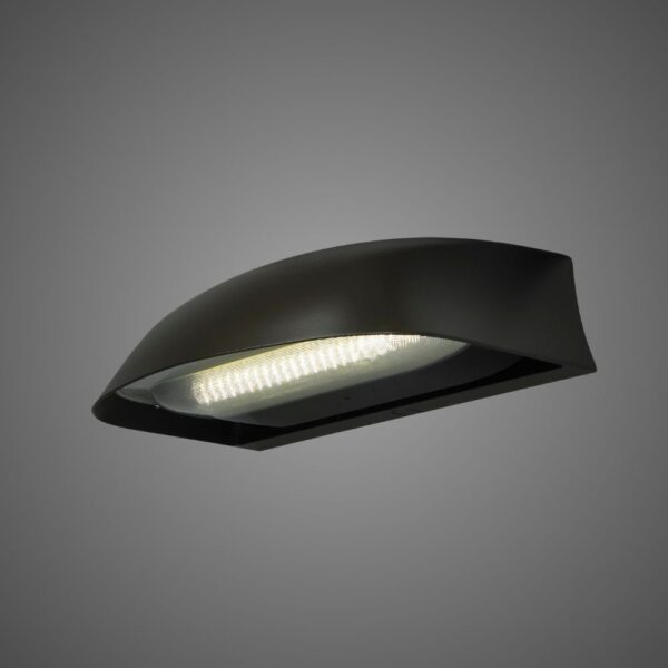
BABA and Buy American Act (BAA) compliant configurations are available for select LEOTEK roadway and traffic lighting products.

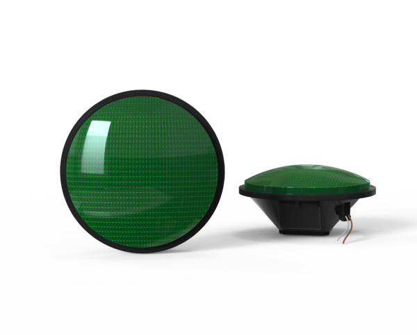
Countdown Signal Module
Hand & Person Overlap
Hand & Person Side by Side
External / Plug-and-Play Smart Node (Mounts externally to the fixture)
Integrable lighting products
Internal / Integrated Smart Node (Built directly inside the luminaire)
Integrable lighting products
The central AI management system (CMS) of the LEOlink Intelligent Lighting System.
Integrable lighting products
Frontier isn’t just a name—it’s a declaration. Born from the legacy of Dialight’s trusted traffic signal designs and reimagined by LEOTEK’s innovation-driven R&D and product management teams, Frontier stands as a symbol of reliability, evolution, and regional adaptation.
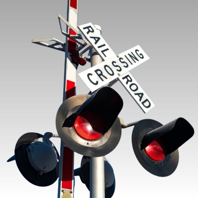
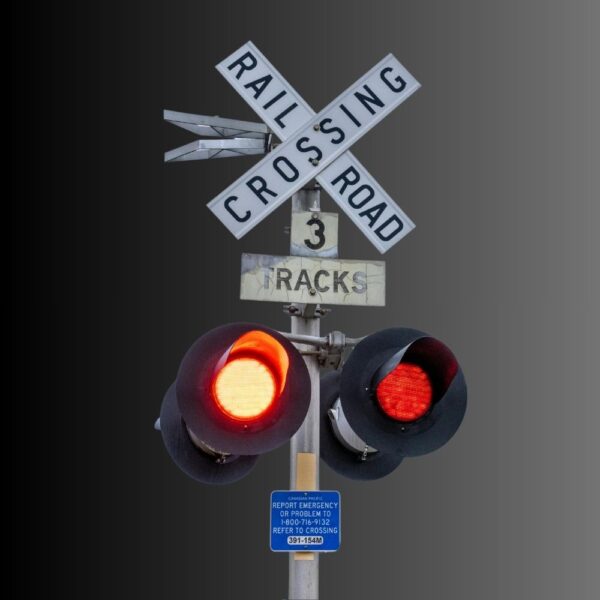
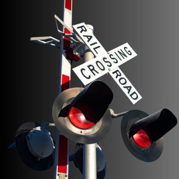
Compare LEOTEK IL Series railroad signal modules for transit indications, grade crossings and special applications. Review model specifications and downloads.
Explore related applications: Railroad signal applications · All Railway Signal products
Check our LEOLab pages to find more information.
If you need any service, please feel free to contact us!
PROJECT SUPPORT
Answers to common questions about product selection, installation and procurement.
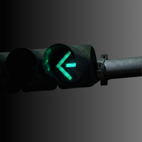
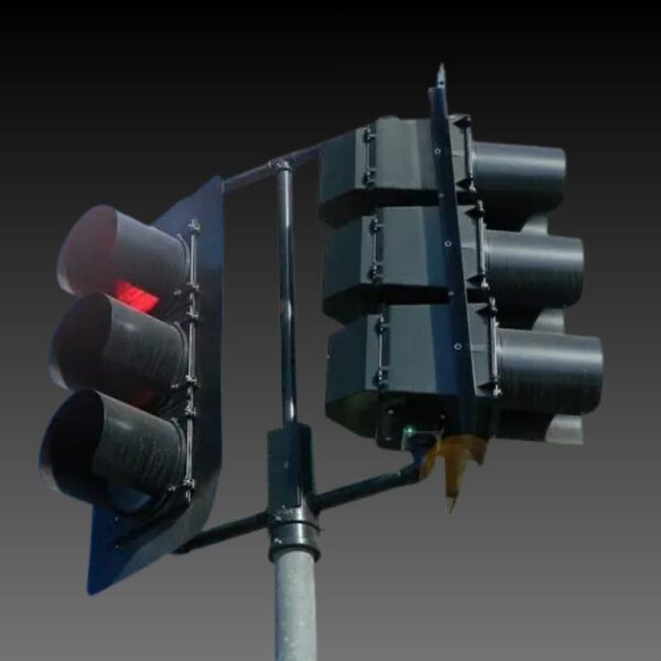
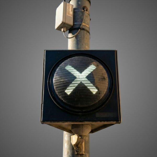
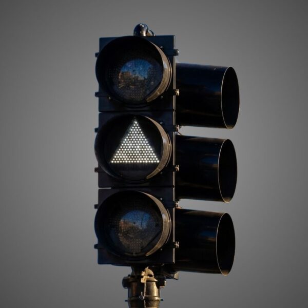
IL crossing is the 12-inch red grade-crossing warning module with red/white side-light choices. Transit covers separate triangle/bar indications in 8/12-inch configurations; special applications cover 12-inch T-Bar and X symbols. Their indications and electrical requirements differ. Select the required railway function before comparing appearance or power, and use that function’s exact model sheet.
Specifications & documents
IL Series Railroad Grade Crossing Module Spec Sheet · IL Series Transit Indications Signal Module Spec Sheet · Special Applications IL Series Signal Module Spec Sheet
The actual IL crossing specification gives 8–20Vdc or 8–16Vac at 50/60Hz. Its Resources folder name uses a different nominal description, so the folder title should not replace the electrical table. Specify the exact module and matching circuit against the sheet, including normal and backup supply conditions. Do not apply transit’s 80–135Vac rating to the crossing module.
Specifications & documents
IL Series Railroad Grade Crossing Module Spec Sheet · IL Series Transit Indications Signal Module Spec Sheet
Further reading
Railroad Crossing Standby Power: Why the Lamp Is Only One Load
TSL-12RCS-ILR-E1 uses red side lights; TSL-12RCS-ILW-E1 uses white side lights. Both listed models have a red crossing warning face and 9W/750mA entries. Side-light color is therefore a specific ordering choice, not a change of the main crossing indication to white. Preserve the full ILR/ILW code in the installed and spare records.
Specifications & documents
IL Series Railroad Grade Crossing Module Spec Sheet
The transit sheet is described on the product page as 80–135Vac, 60Hz, with an 8-inch white triangle and 12-inch red/white indication patterns. That differs from IL crossing’s low-voltage table. Do not connect or order by diameter alone. The exact symbol, supply and circuit function must match the approved railway interface and its model-specific document.
Specifications & documents
IL Series Transit Indications Signal Module Spec Sheet · IL Series Railroad Grade Crossing Module Spec Sheet
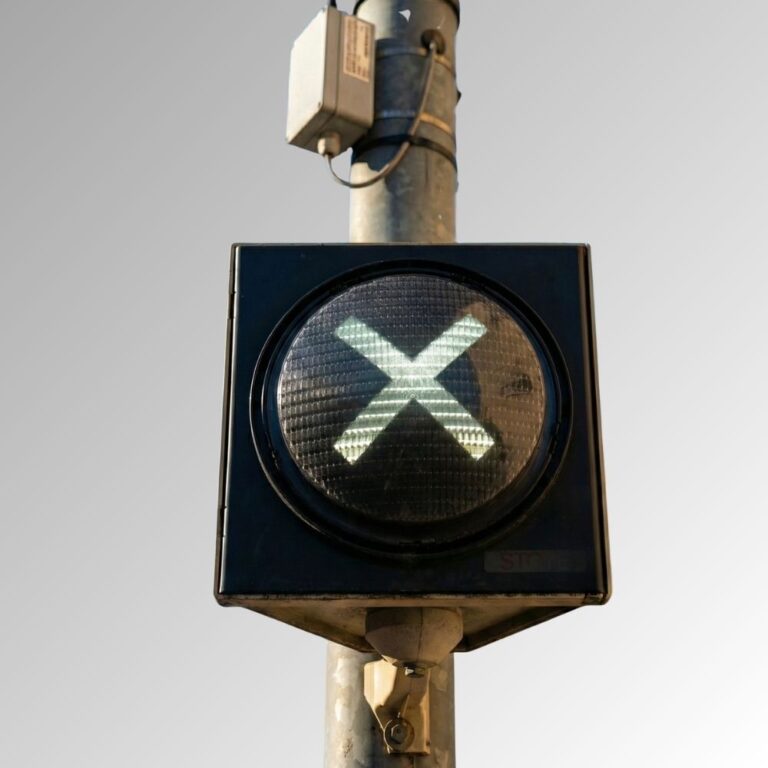
The current product page identifies 12-inch red/green X signs and red/white T-Bars at 6.9W per listed model. It also notes that the attached special-application sheet omits an input-voltage field, while Resources identifies an 80–135Vac configuration. Treat the exact electrical rating as a required model clarification; do not manufacture a universal voltage claim from a folder label or another IL product.
Specifications & documents
Special Applications IL Series Signal Module Spec Sheet
The crossing sheet lists −40°C to +70°C operation, response under 75ms, AREMA Class B environmental references and a hard-coated UV-stabilized lens. These apply to that module sheet, not automatically to every transit or special symbol. Check installation fit and system acceptance with the railway’s required documents instead of using road-traffic specifications as substitute approval evidence.
Specifications & documents
IL Series Railroad Grade Crossing Module Spec Sheet
IL crossing lists five-year limited warranty and a 70% initial-intensity claim at 100,000 operating hours. Those claims describe different matters; neither establishes guaranteed fault-free operation of the crossing system. The separate power-off indicator has three-year limited coverage. Keep warranty, indication function and exact model separate in procurement and maintenance records.
Specifications & documents
IL Series Railroad Grade Crossing Module Spec Sheet · RR POI AC Spec Sheet
Use the intended housing, supply/controller and exact indication/side-light model. Verify the required energized/off states, monitoring and visible presentation across the railway’s accepted operating conditions. Retain the model sheet, circuit drawing and observed results, including backup-supply conditions where applicable. Similar diameter or an AREMA reference alone does not establish interchangeable operation of crossing, transit and special-application modules.
Specifications & documents
IL Series Railroad Grade Crossing Module Spec Sheet · IL Series Transit Indications Signal Module Spec Sheet · Special Applications IL Series Signal Module Spec Sheet
Further reading
Railroad Crossing Standby Power: Why the Lamp Is Only One Load
Select railroad modules by the required indication, circuit interface and approved railroad or transit application. Compare the exact model documents and validate the complete installation under the operator’s procedures.
Compare the IL transit-indication, special-application and grade-crossing modules by their intended function and exact ordering configuration. A shared IL name does not establish the same optical, electrical or circuit requirements.
Review signal housing, mounting, viewing arrangement, wiring and supply with the operator’s signal engineer. Match the proposed module to the circuit and monitoring equipment using the current model-specific documents.
Use the railroad or transit operator’s approved design and acceptance procedures. Document the required indication states, supply conditions and monitoring behavior before expanding a retrofit.
Create a schedule of exact model numbers and required indications, electrical variants, quantities and spare units. Obtain current specifications, installation instructions, applicable approval documentation and written warranty terms. Record the installed configurations so maintenance teams can select the correct replacement.