BABA and Buy American Act (BAA) compliant configurations are available for select LEOTEK roadway and traffic lighting products.
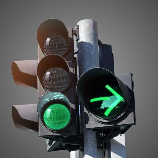
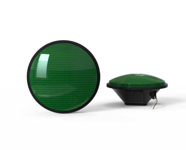
Countdown Signal Module
Hand & Person Overlap
Hand & Person Side by Side
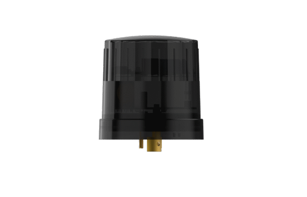
External / Plug-and-Play Smart Node (Mounts externally to the fixture)
Integrable lighting products
Internal / Integrated Smart Node (Built directly inside the luminaire)
Integrable lighting products
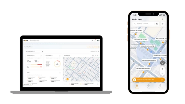
The central AI management system (CMS) of the LEOlink Intelligent Lighting System.
Integrable lighting products
Frontier isn’t just a name—it’s a declaration. Born from the legacy of Dialight’s trusted traffic signal designs and reimagined by LEOTEK’s innovation-driven R&D and product management teams, Frontier stands as a symbol of reliability, evolution, and regional adaptation.
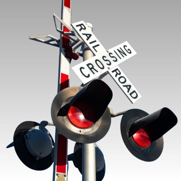
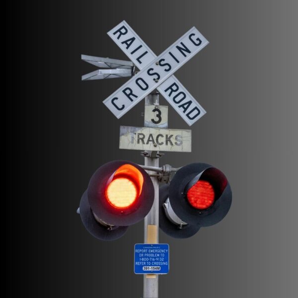
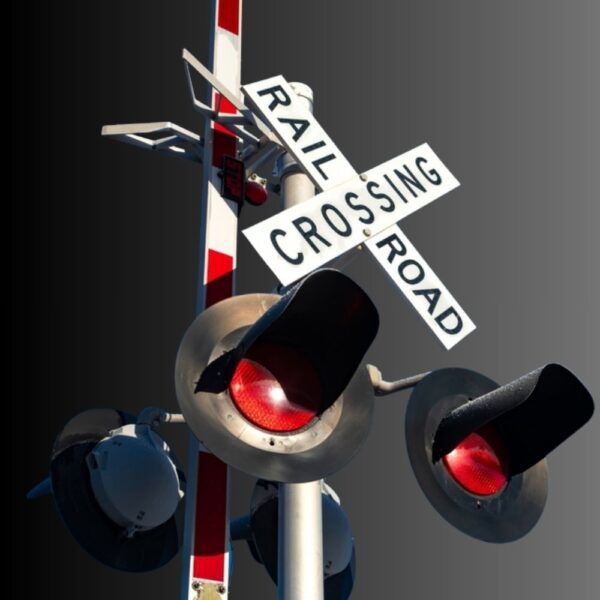
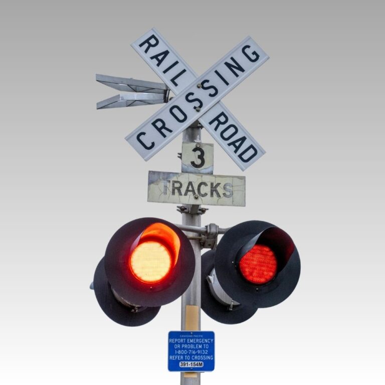
Browse LEOTEK railroad and grade crossing signal products. Compare IL and EV Series modules and power off indicators with specifications and downloads.
Explore related applications: Railroad signal applications
Browse product series:
Check our LEOLab pages to find more information.
If you need any service, please feel free to contact us!
PROJECT SUPPORT
Answers to common questions about product selection, installation and procurement.
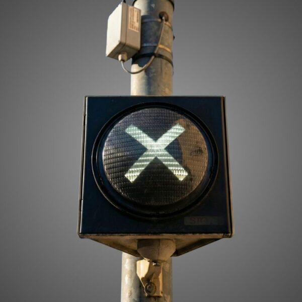
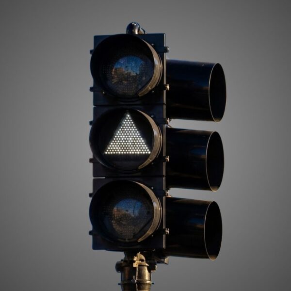
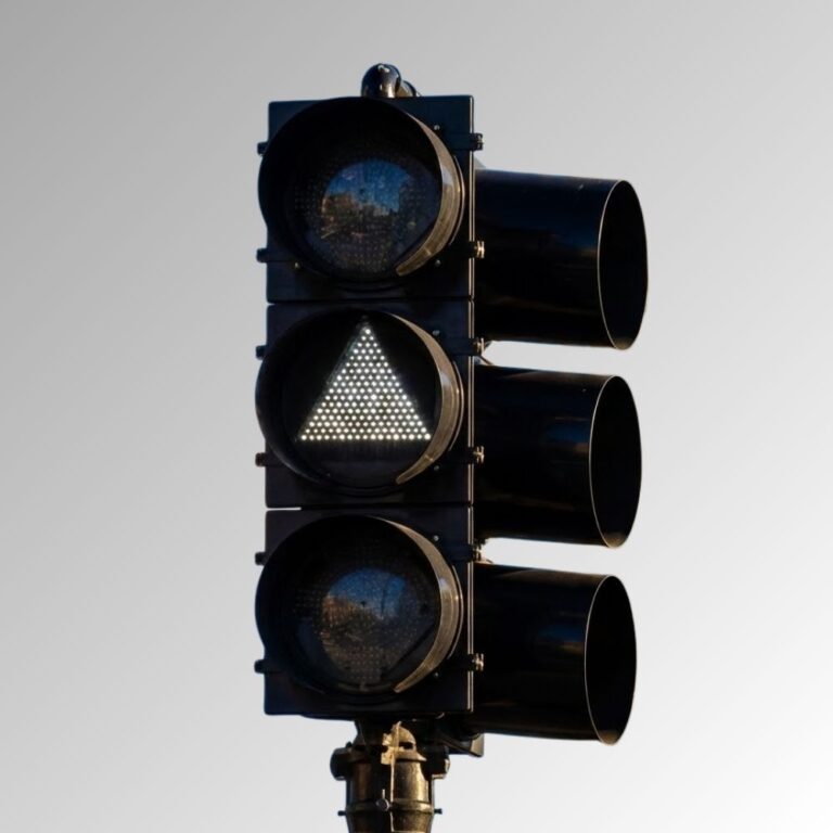
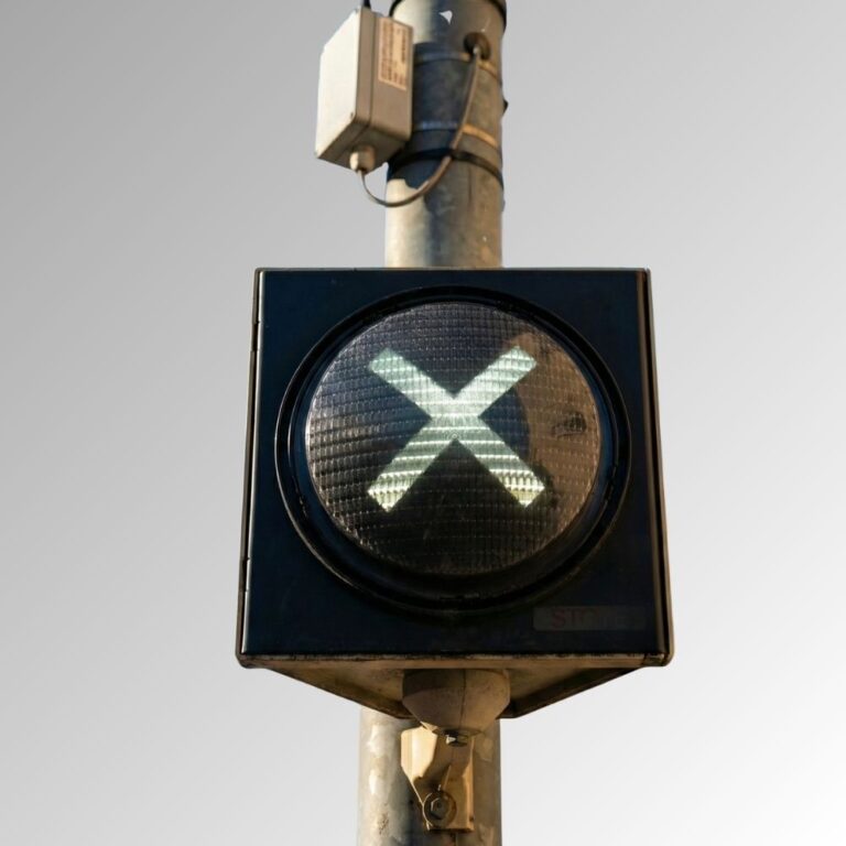
IL and EV crossing products provide red grade-crossing warnings. IL transit provides triangle/bar indications, while IL special applications provide T-Bar/X symbols. The power-off indicator reports a power-monitoring condition; it is not a crossing-warning lens. Choose by the required signal function and circuit before comparing sizes, since this category combines electrically and optically different equipment.
Specifications & documents
IL Series Railroad Grade Crossing Module Spec Sheet · ev series railroad grade crossing module spec sheet · IL Series Transit Indications Signal Module Spec Sheet · Special Applications IL Series Signal Module Spec Sheet · RR POI AC Spec Sheet
No. The power-off indicator is a separate monitoring indication available in red or white, not the 12-inch crossing warning module. Its sheet lists 7–18Vdc operation and a separate AC detection input. Treat the monitored condition and indication function as a distinct equipment line; the presence of a red LED does not establish an interchangeable crossing signal.
Specifications & documents
RR POI AC Spec Sheet · IL Series Railroad Grade Crossing Module Spec Sheet · ev series railroad grade crossing module spec sheet
The power-off unit operates from 7–18Vdc; the separate AC detection input is 55–240Vac. The AC range is not the indicator’s operating-power rating. Its listed white model TSL-POK-WCF-AB1 draws 2.5W and red TSL-POK-RBM-B1 draws 2W. Keep the detection and supply connections distinct in the project drawing and select the exact required model.
Specifications & documents
RR POI AC Spec Sheet
IL crossing’s sheet gives 8–20Vdc/8–16Vac with ILR/ILW side-light models. EV offers linear E1-CC, regulated E1 and unregulated U1 variants; its U1 has a separate 8–14Vdc limit in the sheet. These model tables, not nominal folder labels, should define the review. Similar crossing appearance does not establish identical input behavior on the existing circuit.
Specifications & documents
IL Series Railroad Grade Crossing Module Spec Sheet · ev series railroad grade crossing module spec sheet
Further reading
Railroad Crossing Standby Power: Why the Lamp Is Only One Load
IL crossing lists red or white side lights on a red main warning face; EV also has model-specific red/white side-light choices. Transit and special-application symbols are separate product groups, with triangle/bar or T-Bar/X patterns. Identify the main indication, side-light color and orientation in the procurement line so a general color description does not hide a different function.
Specifications & documents
IL Series Railroad Grade Crossing Module Spec Sheet · ev series railroad grade crossing module spec sheet · IL Series Transit Indications Signal Module Spec Sheet · Special Applications IL Series Signal Module Spec Sheet
Include the exact supply version’s allowable voltage range, operating duty, batteries/charging, environmental conditions and every connected load. EV’s low-wattage feature is not a promised backup duration. The power-off indicator also requires its separate DC supply and AC-detection design. Validate the system’s required operating and recovery conditions with the responsible railway equipment documentation.
Specifications & documents
ev series railroad grade crossing module spec sheet · RR POI AC Spec Sheet
Further reading
Railroad Crossing Standby Power: Why the Lamp Is Only One Load
No. IL/EV crossing sheets list five-year limited warranty and −40°C to +70°C operation. The power-off sheet lists three-year limited warranty and its own environmental and connector information. Transit/special products require their own documents. A category-level “railroad” label must not propagate one product’s coverage, ratings or approval evidence across the full equipment schedule.
Specifications & documents
IL Series Railroad Grade Crossing Module Spec Sheet · ev series railroad grade crossing module spec sheet · RR POI AC Spec Sheet
Separate crossing IL/EV, transit, special symbols and power-off indicators. Record complete order code, supply/version, main/side-light color, housing dimensions, connector and applicable railway acceptance evidence for each. The power-off sheet permits an optional -WG Wago suffix; EV supply suffixes need separate spare lines. This organization supports correct replacement by function and electrical configuration instead of diameter alone.
Specifications & documents
IL Series Railroad Grade Crossing Module Spec Sheet · ev series railroad grade crossing module spec sheet · IL Series Transit Indications Signal Module Spec Sheet · Special Applications IL Series Signal Module Spec Sheet · RR POI AC Spec Sheet
Compare railroad and transit modules by their intended indication, circuit interface and operator requirements. Include the power-off indicator as a distinct circuit-status product when reviewing the complete equipment schedule.
Separate grade-crossing indications, transit indications, special-application modules and power-off indicators in the equipment schedule. Compare the exact IL, EV or indicator model documents for the approved application.
Provide circuit drawings, supply characteristics, monitoring equipment, housing and viewing arrangements to the operator’s signal engineer. Confirm each module’s interface and termination details independently.
Use the railroad or transit operator’s approved acceptance plan for the complete installation. Record the required indication states, circuit conditions and monitoring behavior for each equipment type.
Create a schedule of exact model numbers and required indications, electrical variants, quantities and spare units. Obtain current specifications, installation instructions, applicable approval documentation and written warranty terms. Record the installed configurations so maintenance teams can select the correct replacement.