TOP BAR
IL6 Series

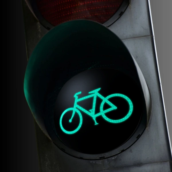
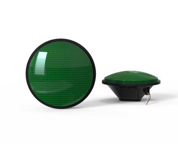
IL6 Series Traffic Signal Module – Bicycle Indication

RoHS compliantISO 9001 Registered

Availability varies by configuration; see the specification sheet.

The IL6 Series LED bicycle traffic signal module presents a dedicated bicycle indication in 8-inch and 12-inch formats. The published bicycle specification covers red, yellow and green models for 80–135 Vac, 60 Hz signal cabinets.

Choose the color and size by order code; listed power ranges from 5.6 to 7.0 W. The sheet specifies a tinted lens only. A 10–28 Vdc bicycle variant is not documented in the available bicycle sheet, so it should not be assumed from this product page.

Features

Configuration & Electrical

  • 8-inch and 12-inch dedicated bicycle indications in red, yellow and green.
  • 80–135 Vac, 60 Hz input; 5.6–7.0 W across the six listed models.
  • Tinted lens only in the available IL6 bicycle specification.

Optics & Field Performance

  • Hard-coated UV-stabilized lens, O-ring moisture seal and engineered aluminum heat sink.
  • Constant-current source supports uniform optical output; <75 ms response is listed.
  • Published 70% initial intensity at 100,000 hours and five-year limited warranty.

Selection & Related Resources

Specifications

Color
Red, Green, Yellow
Indication
Bicycle
Lens Color
Tinted
Lens Size
8", 12"
Voltage
120Vac (80-135Vac)

Application & design reference

Bicycle signal faces: preserve the road-user message

A bicycle-symbol signal face is a dedicated application. The symbol, complete face arrangement and intersection operation need to agree before a replacement module is selected.

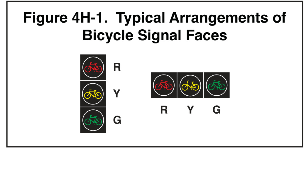
MUTCD Figure 4H-1: Typical Arrangements of Bicycle Signal Faces.
Source: FHWA, MUTCD 11th Edition with Revision 1 (December 2025), Figure 4H-1, printed p. 715 / PDF p. 756. Original figure and provisions. Select the image to read the full-resolution labels and notes.

What the bicycle symbol changes

Figure 4H-1 shows vertical and horizontal bicycle signal-face arrangements. Section 4H.06 specifies bicycle-symbol indications throughout the bicycle face; it does not treat ordinary circular or arrow indications as interchangeable substitutes within that face.

The drawing helps review the displayed message. It does not establish the voltage, dimensions or optical performance of an offered module. Match the required size and input to the exact product sheet, and keep the complete head and installation details in the project review.

  • Identify the bicycle movement and the intended face orientation.
  • Review the associated signs, placement and operating sequence under Chapter 4H.
  • Confirm model, lens, voltage and head compatibility from the supplied documents.
Can bicycle symbols be mixed with ordinary circular indications in the same face?

Section 4H.06 calls for all bicycle-symbol indications in a bicycle signal face. Use the original provision and the agency-approved design when reviewing a proposed arrangement.

Does an available module establish a complete bicycle crossing design?

The module supplies an indication. Placement, signs, visibility, timing and integration with the other road users belong to the complete intersection design and require their own review.

Discuss the required configuration with LEOTEK

Resources

Related Products

LD Arrow Traffic light module
Indication: Arrow
Voltage: 120Vac (80-135Vac)
PV Series LED module (3)
Indication: Ball
Voltage: 70-135Vac
IL6-P3 Series 12″ Traffic Signal Module – Ball (3)
Indication: Ball
Voltage: 120Vac (80-135Vac), 10-28Vdc, 48Vdc (36-60Vdc)
IL6-P3 Series Traffic Signal Module – Arrow
Indication: Arrow
Voltage: 120Vac (80-135Vac)

LEOTEK's Cases

Looking for More Information?
Connect with LEOTEK

Need a quote or more details about our collaboration? At LEOTEK, we’re ready to provide you with professional advice and friendly service, bringing you closer to a smart and sustainable future.

English
Español
繁體中文