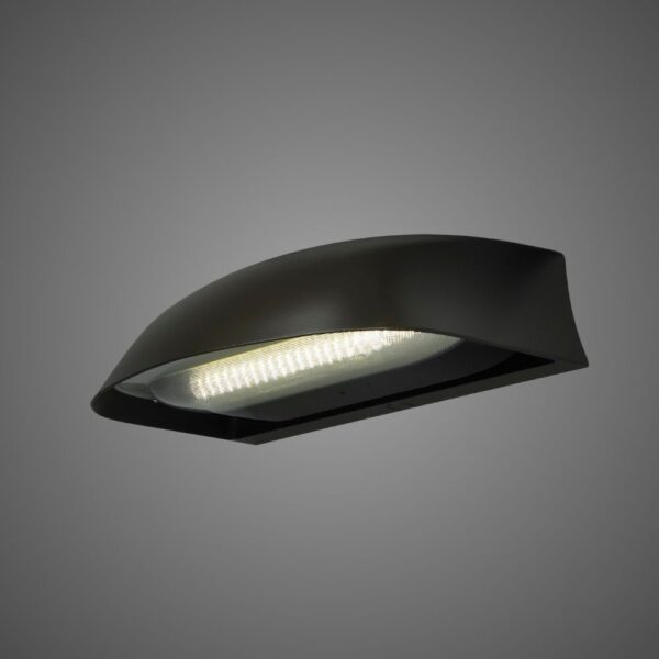
BABA and Buy American Act (BAA) compliant configurations are available for select LEOTEK roadway and traffic lighting products.
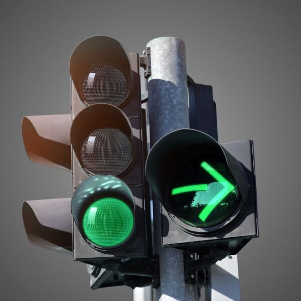
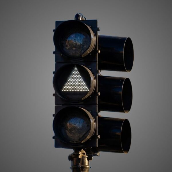
Countdown Signal Module
Hand & Person Overlap
Hand & Person Side by Side
External / Plug-and-Play Smart Node (Mounts externally to the fixture)
Integrable lighting products
Internal / Integrated Smart Node (Built directly inside the luminaire)
Integrable lighting products
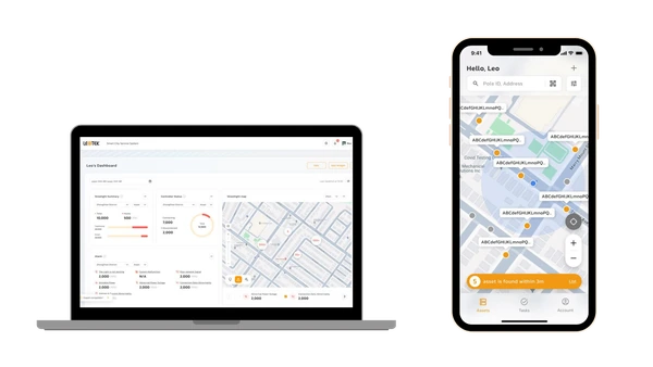
The central AI management system (CMS) of the LEOlink Intelligent Lighting System.
Integrable lighting products
Frontier isn’t just a name—it’s a declaration. Born from the legacy of Dialight’s trusted traffic signal designs and reimagined by LEOTEK’s innovation-driven R&D and product management teams, Frontier stands as a symbol of reliability, evolution, and regional adaptation.
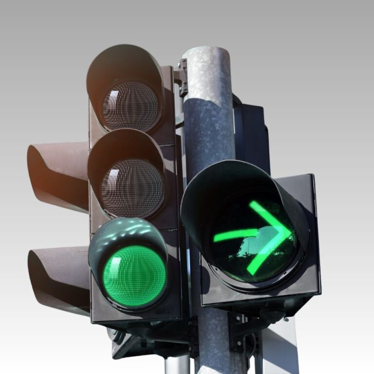
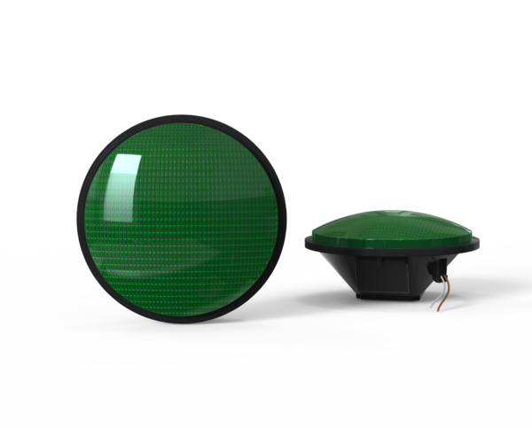
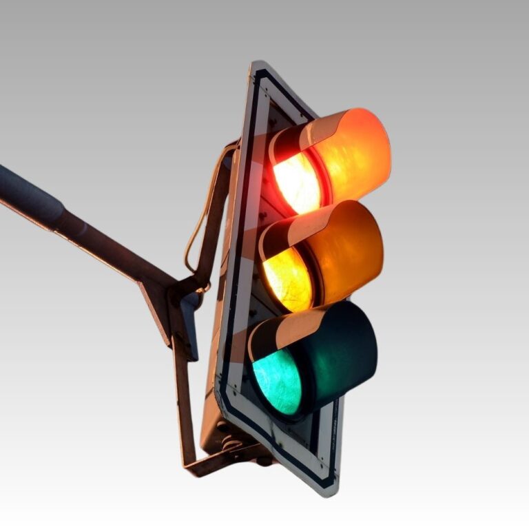
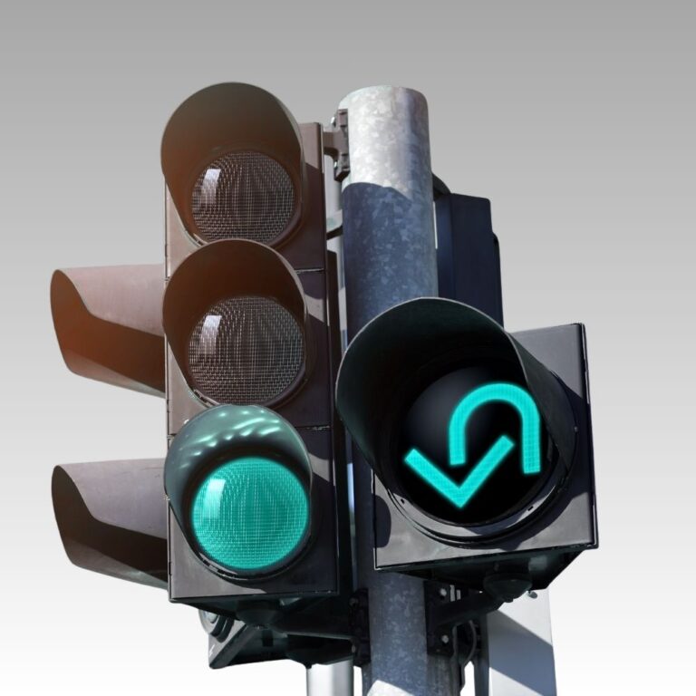
Compare LEOTEK IL6-P3 traffic signal modules for ball, arrow and U-turn indications. Review model specifications and download supporting product documents.
Explore related applications: Traffic signal applications · All Traffic Signal products
Check our LEOLab pages to find more information.
If you need any service, please feel free to contact us!
PROJECT SUPPORT
Answers to common questions about product selection, installation and procurement.
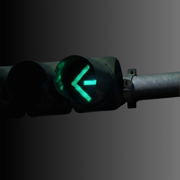
Ball models provide circular indications in 8-inch and 12-inch formats. Standard arrows use directional-arrow optics, with available sizes depending on voltage. U-turn is a separate 12-inch indication with its own sheet, not a standard arrow rotated in the housing. Choose the indication geometry first, then match size, color, voltage suffix and lens option to the agency signal plan.
Specifications & documents
IL6-P3 Series Traffic Signal Module – Ball · IL6-P3 Series Traffic Signal Module – Arrow · IL6 P3 U Turn Arrow Spec Sheet
Further reading
Traffic Signal Approval: ITE, ETL and DOT Lists
Ball variants cover 8/12-inch AC 80–135Vac, DC 10–28Vdc and 48V-system 36–60Vdc models. Standard-arrow AC and 48V sheets cover 12-inch models; the 10–28Vdc arrow sheet covers 8-inch and 12-inch versions. U-turn’s published sheet covers 12-inch 80–135Vac only. These separate model variants must not be interpreted as one universal-input product or as every size being available at every voltage.
Specifications & documents
IL6-P3 Series Traffic Signal Module – Ball · IL6-P3 Series Traffic Signal Module – Arrow · IL6 P3 U Turn Arrow Spec Sheet
Further reading
Traffic Signal Approval: ITE, ETL and DOT Lists
The ball and standard-arrow documents identify tinted lenses as standard and a model-specific -CLR clear-lens suffix. That should not be extended automatically to another symbol or voltage variant. Record the exact lens option with the size/color/voltage model and check its applicable approval evidence. A clear or tinted lens affects the ordered optical configuration, not just the procurement description.
Specifications & documents
IL6-P3 Series Traffic Signal Module – Ball · IL6-P3 Series Traffic Signal Module – Arrow
The A1 AC, B1 low-voltage DC and L1 48V-system variants have separate electrical tables. Review the selected model’s supply, current/power, switching response and off-state characteristics against the actual load switch and monitoring equipment. For the U-turn AC version, published response is under 75ms and turn-off voltage above 35Vac. A family-level voltage list cannot establish compatibility of a specific replacement circuit.
Specifications & documents
IL6-P3 Series Traffic Signal Module – Ball · IL6-P3 Series Traffic Signal Module – Arrow · IL6 P3 U Turn Arrow Spec Sheet
Further reading
Traffic Signal Approval: ITE, ETL and DOT Lists
The published U-turn table lists 12-inch red, yellow and green A1 models at 80–135Vac, drawing 5.5W, 6.6W and 6.8W respectively. It does not document a 10–28Vdc U-turn model. Specify the U-turn order code and its own optical document; the standard-arrow DC options cannot be used as evidence that the same DC U-turn configuration is available.
Specifications & documents
IL6 P3 U Turn Arrow Spec Sheet
IL6-P3 documents five-year limited coverage and an LED intensity-maintenance claim; DT ball/arrow documents 15-year limited full-performance coverage with an extended-life LED/power-supply design. Compare equivalent indication, size, supply and lens choices, plus purchase, energy, maintenance and traffic-control costs. A 100,000-hour intensity claim is not the same as a 15-year whole-module warranty or a guaranteed replacement interval.
Specifications & documents
IL6-P3 Series Traffic Signal Module – Ball · IL6-P3 Series Traffic Signal Module – Arrow · DT series traffic signal module ball · DT 12” 80-135Vac Arrow Spec Sheet
Further reading
Long-Life LED Traffic Signals: Replacement Cost and ROI
Do not assume that. The published AC ball and standard-arrow pages identify ETL-verified A1 entries; B1 and L1 need their own applicable approval evidence. Keep the matching voltage-specific sheet and exact order code in the submittal. A test/listing statement for an AC model is not evidence that an electrically different DC model meets the same procurement approval.
Specifications & documents
IL6-P3 Series Traffic Signal Module – Ball · IL6-P3 Series Traffic Signal Module – Arrow
Further reading
Traffic Signal Approval: ITE, ETL and DOT Lists
Record indication, 8/12-inch size, color, A1/B1/L1 supply suffix, lens suffix, connector and tested cabinet configuration. Include the actual voltage-specific sheet and settings used during commissioning. For U-turn, retain its separate model identity and 80–135Vac rating. These details prevent a visually similar spare from being selected solely by diameter or family name when its electrical or optical configuration differs.
Specifications & documents
IL6-P3 Series Traffic Signal Module – Ball · IL6-P3 Series Traffic Signal Module – Arrow · IL6 P3 U Turn Arrow Spec Sheet
Further reading
Traffic Signal Approval: ITE, ETL and DOT Lists
Compare ball, arrow and U-turn modules by exact indication, physical format and electrical configuration. Plan a documented cabinet and housing compatibility review before a wider retrofit.
Select the ball, arrow or U-turn indication required by the approved design. Confirm lens format, color, electrical rating and ordering code for each module; family-level options do not apply automatically to every indication.
Check existing signal-head dimensions, attachment hardware, wiring and cabinet supply. Review the proposed configuration with load switching and monitoring equipment used by the project.
Use the agency acceptance procedure to verify normal indication operation, required cabinet monitoring behavior and any specified flash, preemption or recovery conditions. Retain the test record with the installation schedule.
Create a schedule of exact model numbers and required indications, electrical variants, quantities and spare units. Obtain current specifications, installation instructions, applicable approval documentation and written warranty terms. Record the installed configurations so maintenance teams can select the correct replacement.