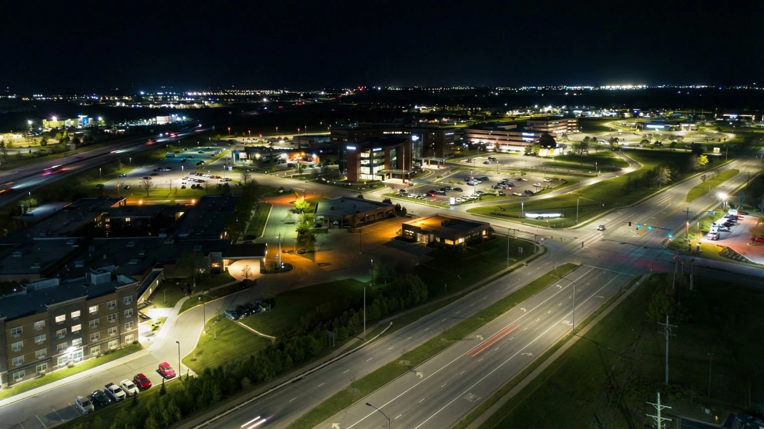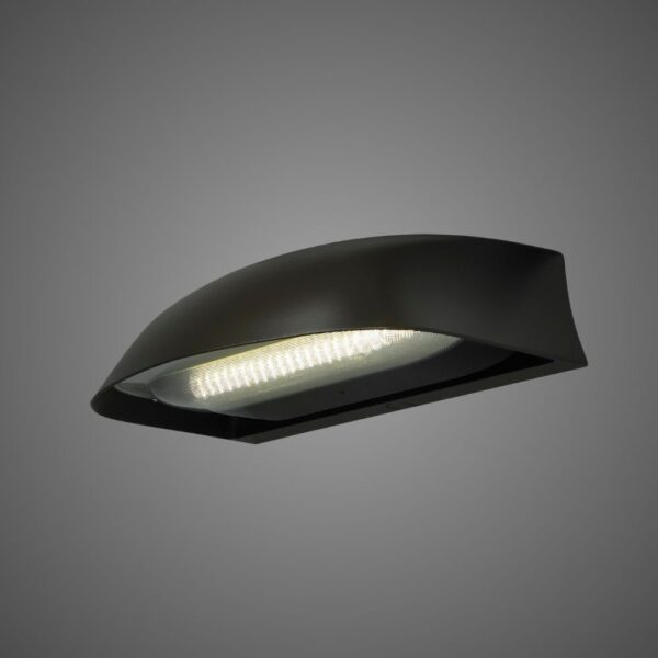
BABA and Buy American Act (BAA) compliant configurations are available for select LEOTEK roadway and traffic lighting products.
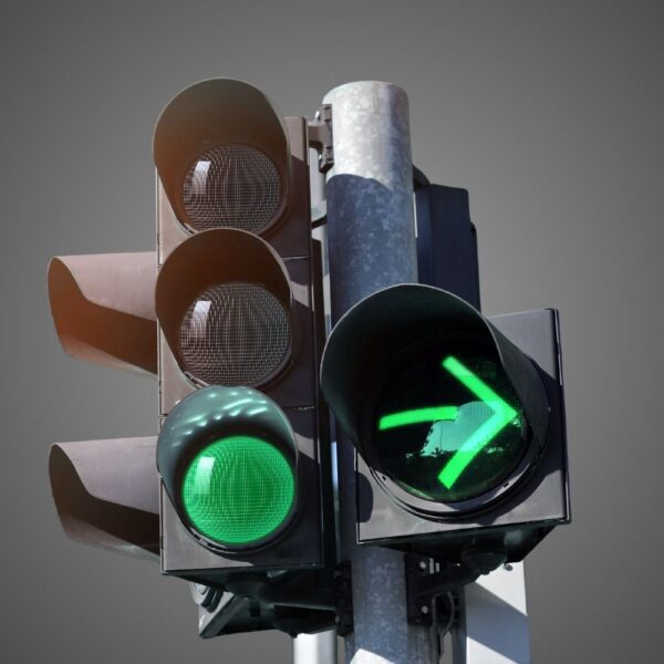
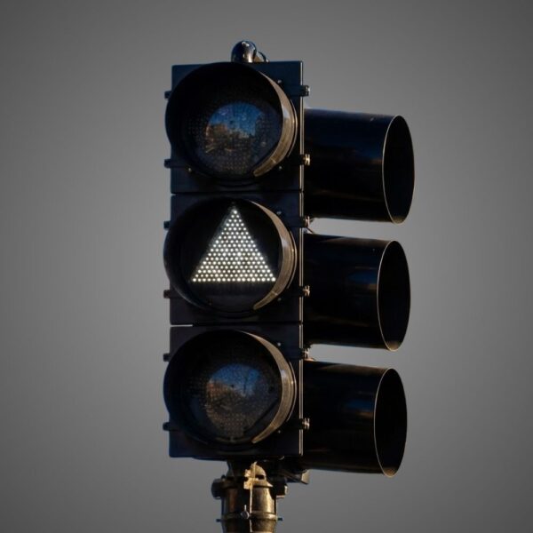
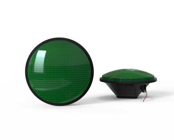
Countdown Signal Module
Hand & Person Overlap
Hand & Person Side by Side
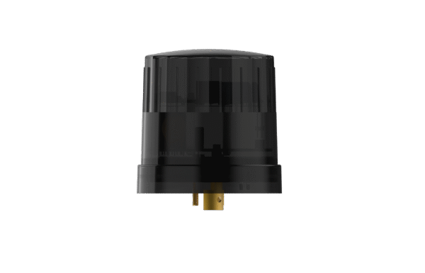
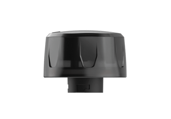
External / Plug-and-Play Smart Node (Mounts externally to the fixture)
Integrable lighting products
Internal / Integrated Smart Node (Built directly inside the luminaire)
Integrable lighting products
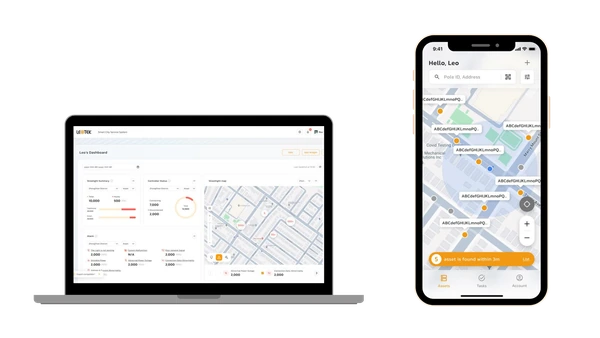
The central AI management system (CMS) of the LEOlink Intelligent Lighting System.
Integrable lighting products
Frontier isn’t just a name—it’s a declaration. Born from the legacy of Dialight’s trusted traffic signal designs and reimagined by LEOTEK’s innovation-driven R&D and product management teams, Frontier stands as a symbol of reliability, evolution, and regional adaptation.


Availability varies by configuration; see the specification sheet.
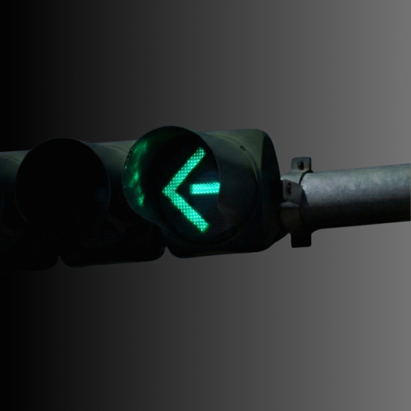
The DT Series extended-life 12-inch LED traffic signal arrow supplies red, yellow and green directional indications for compatible signal heads. Its dedicated thermal and power-supply design targets longer replacement intervals for municipal and DOT signal assets.
The DT arrow specification lists 80–135 Vac operation, 6 W red, 10 W yellow and 6.8 W green model draws, Intertek ETL verification and a 15-year limited full-performance warranty. Match indication color, lens option and housing to the selected order code.
Application & design reference
The lane, complete face and operating mode determine which message an arrow must communicate. Use the approved design, then verify the exact module and control interfaces.

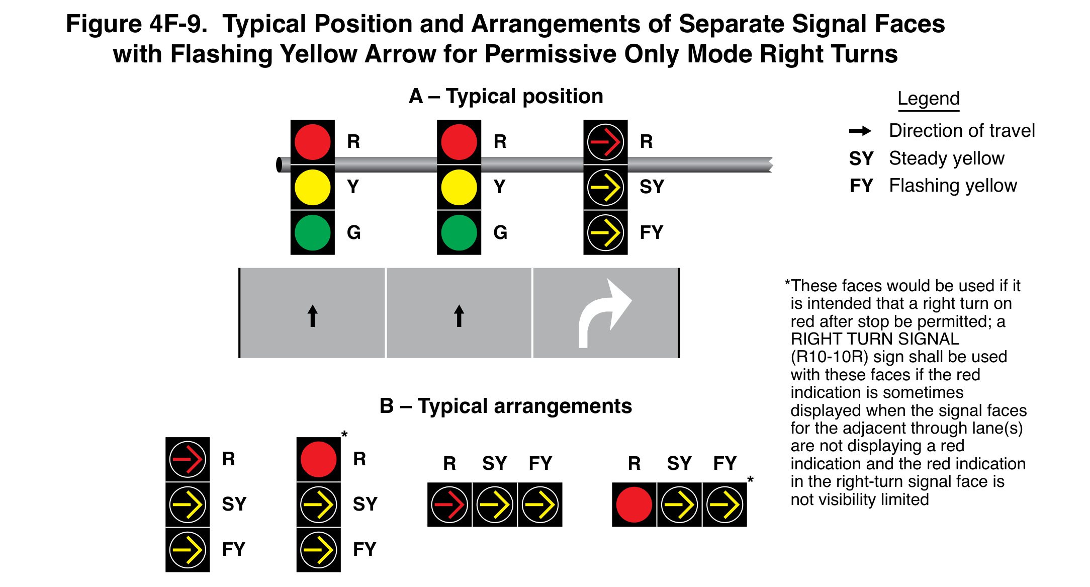
Figure 4F-9 shows a flashing-yellow-arrow arrangement for permissive-only right turns. Section 4F.11 requires a mandatory right-turn lane for a separate face and does not permit a circular green indication in that face during the mode.
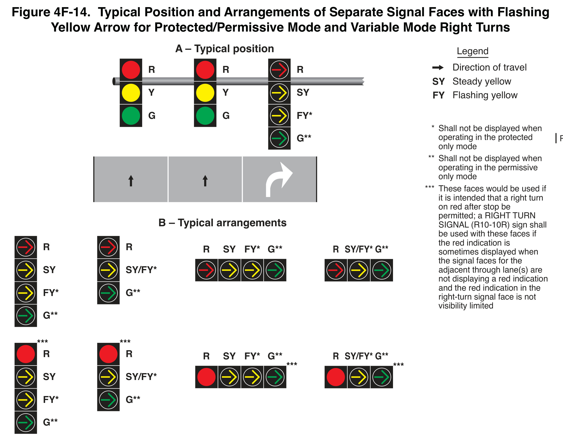
Keep the steady/flashing legend and red-indication note with the arrangement. Where a circular red can be seen by through drivers while their faces are not red, the stated sign or visibility-limitation provision matters.
The drawing does not establish that every yellow-arrow module supports the illustrated functions. Verify the exact model, input, functions and compatibility for the project.

Figure 4F-14 distinguishes protected green-arrow and permissive flashing-yellow-arrow displays. Its asterisks identify indications suppressed in particular modes. Preserve those qualifications when comparing configurations.
A steady photograph cannot verify flashing behavior or the transition between modes. The submittal should identify the complete face, controller configuration, pedestrian and vehicle conflicts, and required compatibility evidence.
Read the complete right-turn guide with four MUTCD arrangements.
The module is one component. Verify the required functions, complete face, controller, wiring and compatibility. A model listing or a matching opening does not establish the entire operating sequence.
The separate-face provisions require a mandatory right-turn lane. Combined lanes have their own restrictions under Section 4F.09; do not transfer a separate-lane arrangement without the design review.
No. Identify the particular steady, flashing and color functions required. Obtain documentation for the proposed configuration and its electrical/control interface.
No. They are original MUTCD application figures. Use the approved project design and the exact equipment documentation for installation, operation and acceptance.
Need a quote or more details about our collaboration? At LEOTEK, we’re ready to provide you with professional advice and friendly service, bringing you closer to a smart and sustainable future.