



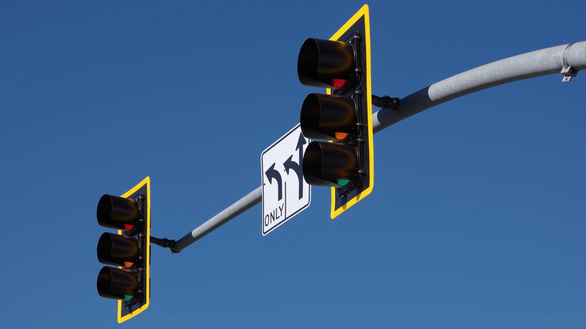
How do traffic signals work? A controller allocates time to compatible movements, using an approved timing plan and, where provided, detector inputs. Signal heads communicate the resulting instructions. The LED module is the visible output; detection, timing, monitoring and power belong to the wider system.
That distinction matters when an intersection receives a complaint. A long wait, an unreadable arrow and a failed indication may look like one “traffic light problem” to a road user, but they lead to different investigations. Replacing a module cannot correct a missed detector call, and retiming cannot repair a failed optical unit.
This guide follows a US signalized intersection from the roadside hardware to its operating sequence. The display references use the MUTCD, 11th Edition with Revision 1, December 2025. Older FHWA diagrams are identified as teaching illustrations; project decisions also need the owning agency’s applicable requirements.
Start with the system behind the signal head
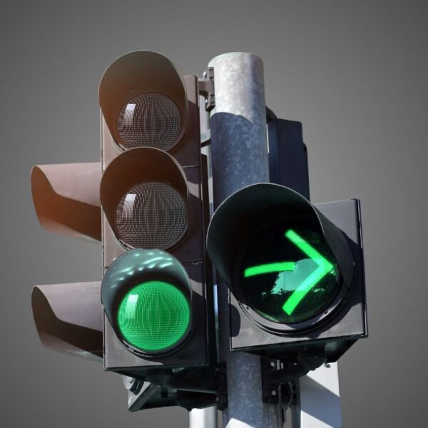
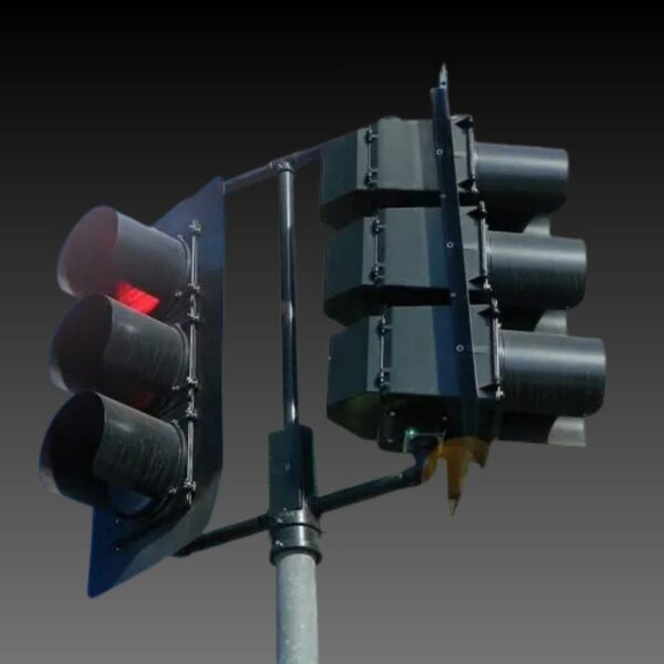
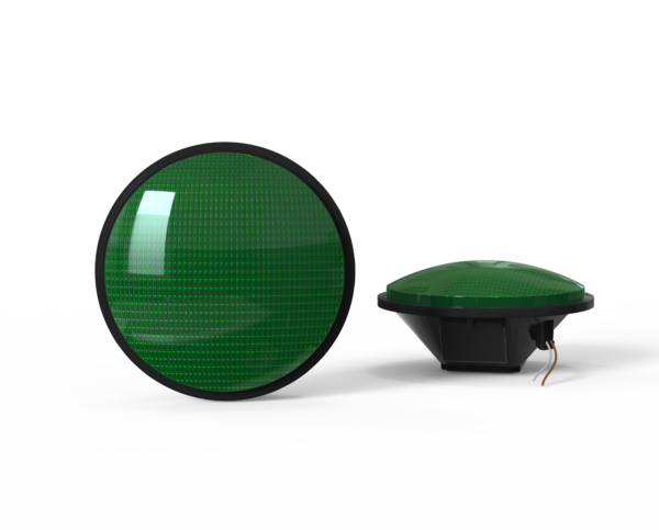
Four terms are easily mixed up in an equipment discussion. An indication is the message being displayed, such as a circular green or flashing yellow arrow. A signal face is the set of indications directed toward a particular movement or approach. A signal head is the assembly carrying one or more faces. An LED module is a replaceable optical unit within that assembly.
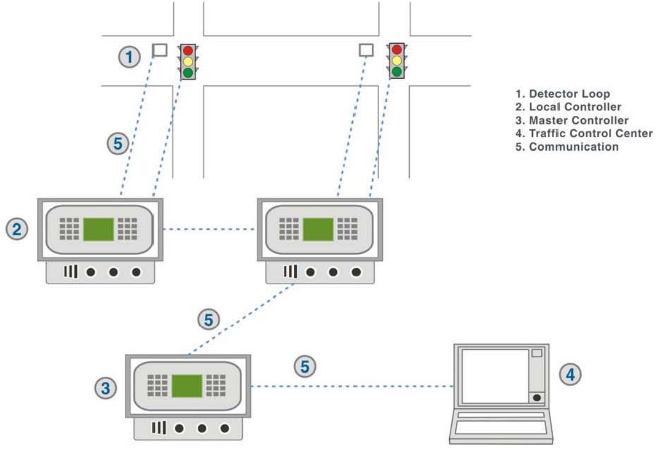
A complete signal system extends beyond those assemblies. Detection reports demand; the local controller applies timing logic; cabinet equipment handles power, switching and monitoring. Communications can connect intersections and a management center. The FHWA schematic below includes an optional master controller, illustrating one architecture rather than a mandatory arrangement for every installation.
Swipe the diagram sideways on small screens, or open the full-size JPEG below.
Open full-size diagram
Follow the numbered connections before following the colored light. Which device detects the waiting vehicle? Where does the request enter the controller? Which component produces the field output? Those questions give the maintenance and operations teams a shared starting point. The photograph or wiring record for the actual cabinet is still needed to identify the installed equipment.
Why one green lasts longer than another
A signal is not necessarily repeating the same stopwatch sequence all day. In pre-timed operation, the planned intervals are fixed for the operating plan. In actuated operation, detector calls influence service within programmed limits. Semi-actuated control typically detects selected movements; fully actuated control provides detection for the movements being actuated. These are operating choices, not different colors of signal hardware.
A call means that service is requested. It does not necessarily mean the requested movement receives an immediate green. The controller may need to finish another movement’s service, pedestrian timing and the required transition before serving the call.
| What the team observes | What to investigate |
|---|---|
| A movement keeps receiving service with no apparent users | Detector state, recall settings and the intended operating plan. |
| Waiting traffic is not served as expected | Whether the correct detection zone generates a call, and whether the controller receives it. |
| Green ends while vehicles are still approaching | Timing settings, detector placement, approach conditions and the reason the phase ended. |
These are diagnostic questions, not diagnoses from observation alone. For example, a vehicle outside the configured detection zone and a failed detector can both produce an apparent missed call. Confirm the field condition and event record before changing equipment or timing.
Read the phase plan before judging the sequence
A movement describes what a road user does, such as turning left or crossing a leg of the intersection. A phase is a controller timing unit serving one or more movements. An interval is a period during which the relevant indications remain unchanged. A phase can contain vehicle and pedestrian timing; it is not simply another name for a green lamp.
Swipe the diagram sideways on small screens, or open the full-size JPEG below.
Open full-size diagram
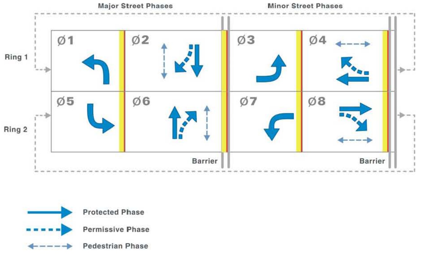
Read this ring-and-barrier example from left to right. Phases within one ring run sequentially. The two rings can serve compatible movements concurrently. Before crossing a barrier to the other street’s service, both rings must be ready to make that transition. In the illustrated numbering, phases 1 and 2 occupy the same ring and run in sequence; phases 2 and 6 can serve compatible opposing through movements.
The phase numbers and assignments must match the actual intersection plan. The diagram is not drawn as a seconds-based timing chart, and it does not supply yellow or red-clearance settings. It helps the reviewer check movement compatibility and sequence before discussing duration.
Turning movements need the right display and operating mode
A circular green permits movements subject to the applicable yielding requirements; it is not an assurance that every possible conflict has disappeared. A protected turn and a permissive turn therefore need different explanations. Under protected service, the turn receives a dedicated arrow indication. Under permissive service, the turning driver must find an acceptable opportunity and yield as required.
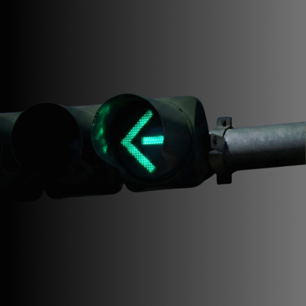
A flashing yellow arrow communicates permissive turning service. A steady yellow arrow communicates a change in the permitted movement. A still photograph of an illuminated yellow arrow cannot establish which mode is operating; the sequence and controller configuration matter.
Swipe the diagram sideways on small screens, or open the full-size JPEG below.
Open full-size diagram
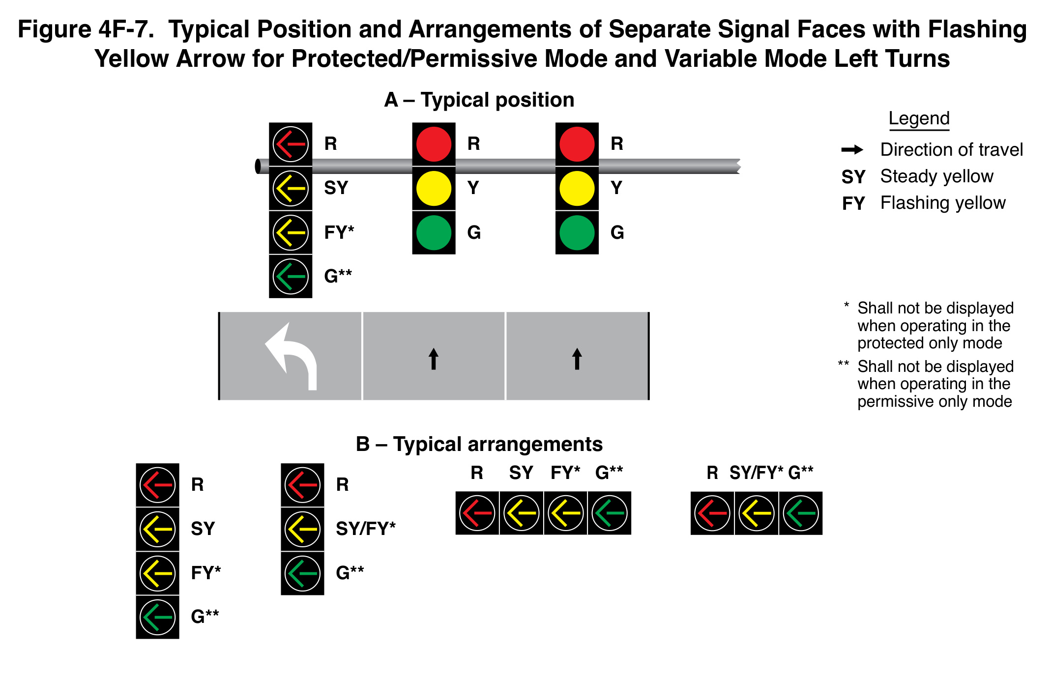
Figure 4F-7 illustrates positions and arrangements for protected/permissive and variable-mode left turns. Read its legend and asterisked restrictions together. The illustrated faces are not a menu from which sections can be removed without reviewing the intended mode.
Left-turn sequencing also needs care. Leading, lagging and lead-lag arrangements interact with the display and opposing traffic service. A “yellow trap” can arise when a permissive left-turn driver incorrectly assumes opposing through traffic is also stopping. Merely choosing a named sequence does not prove that the problem is resolved. Review the display logic, movement plan and actual transitions together.
Pedestrian signals have their own intervals
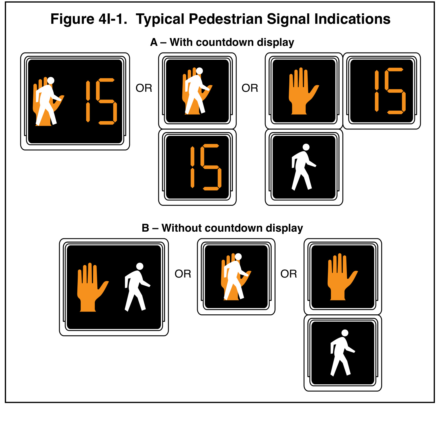
US pedestrian signals use a white walking-person symbol and a Portland-orange upraised hand, rather than the red/green pedestrian convention used in some other countries. The walking-person indication permits a pedestrian to start crossing, while turning vehicles may still need to yield. A flashing hand means pedestrians should not start, while those already crossing continue toward the far side or appropriate refuge. A steady hand means do not enter the roadway.
Open full-size diagram
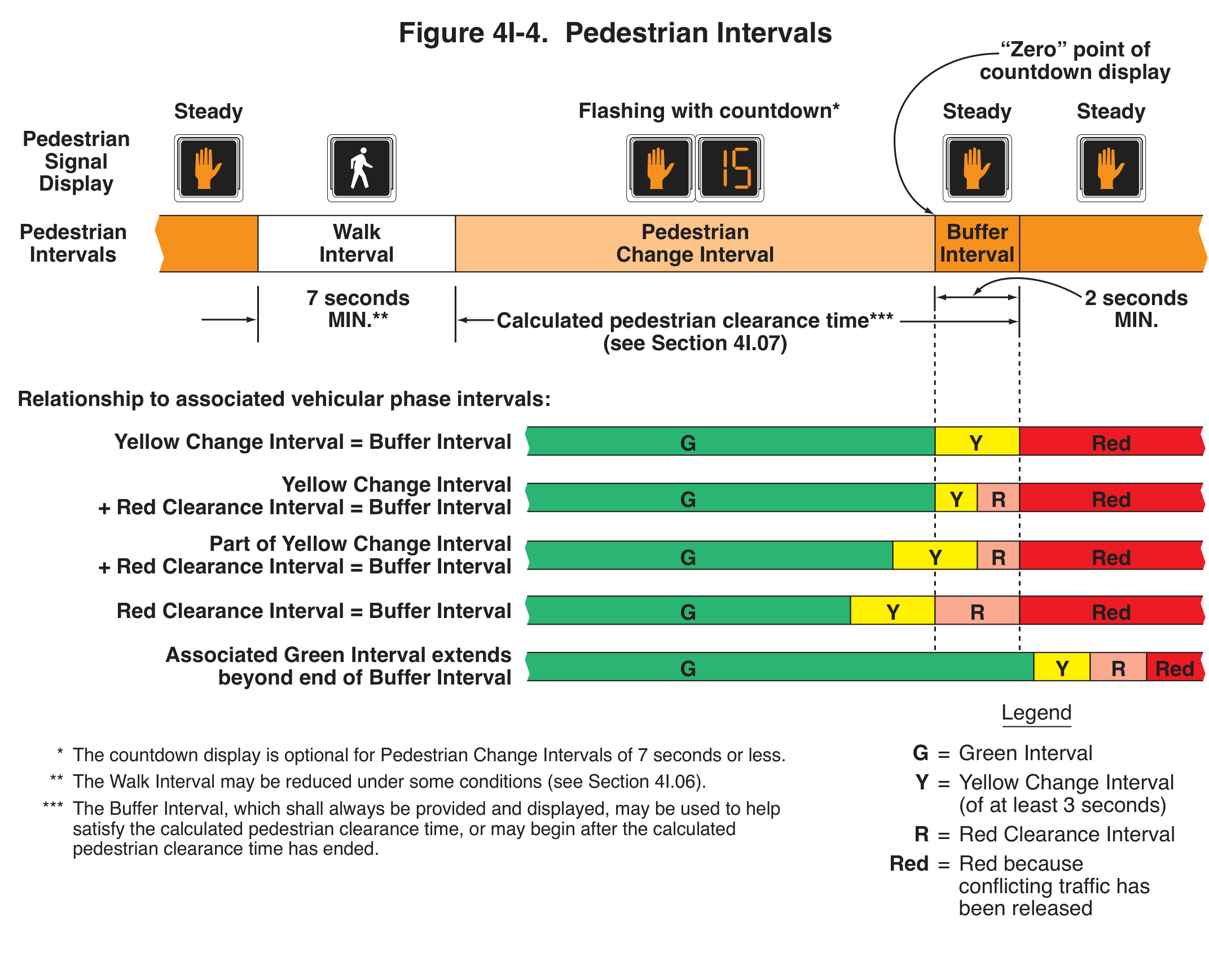
The countdown belongs to the pedestrian change interval. It is not a general timer for the vehicle green, the entire signal cycle or all time available in the pedestrian clearance calculation. That distinction is important both for public-facing explanations and when reviewing a replacement countdown module.
Swipe the diagram sideways on small screens, or open the full-size JPEG below.
Open full-size diagram
In Figure 4I-4, follow the pedestrian display across the upper band and compare it with the alternative vehicle-phase relationships below. The countdown reaches zero at the end of the pedestrian change interval. A buffer interval is still provided. The full figure explains why the displayed number cannot be substituted for the complete clearance-time calculation.
A procurement review should therefore ask how the proposed module works with the installed controller sequence, not just whether it fits the opening. Also review accessible pedestrian signals and detectors: audible and vibrotactile information serve users who cannot rely on the visual display. See the pedestrian countdown timing guide for the detailed interval discussion.
Visibility depends on the installed approach
A functioning module can still be difficult to recognize if the face is poorly aimed, obscured, visually cluttered or associated with the wrong lane. Review the driver’s approach and decision position, including curves, grade, supports, signs and adjacent signal faces. The question is whether the intended user can identify the applicable indication at the needed location.
Indication size is part of that review. The MUTCD establishes requirements and specific exceptions; an existing 8-inch unit does not by itself justify the same choice for new work. Our 8-inch versus 12-inch signal guide explains the decision in more detail.
What an LED retrofit changes—and what it leaves to the system
An LED module replacement changes an optical component. It does not inherently change detection, add adaptive control or correct the phase plan. Review the exact indication, input supply, mounting fit, connector arrangement, operating environment and agency acceptance requirements for the proposed order code.
Electrical and control compatibility deserve a separate check from physical fit. A unit can fit a housing while the overall configuration still needs review against the cabinet outputs, monitoring arrangements and installation instructions. For countdown equipment, include the required sequence and available model settings in that review.
| Submittal item | Useful evidence |
|---|---|
| Exact model and configuration | Order code, indication, nominal size, input and applicable drawings. |
| Agency acceptance | Current approved-product entry and its scope, where required. |
| Installed compatibility | Housing, connection, cabinet and operating-sequence review. |
| Closeout and maintenance | Field checks, asset record, replacement procedure and warranty terms. |
For an energy comparison, calculate the energized hours of each indication and identify what equipment the comparison includes. Module input power and total cabinet energy are different boundaries. The LED signal energy guide walks through that distinction. For purchasing, verify the approved-product listing rather than relying on a general claim about a product family.
Connected signals still need an operating objective
Corridor coordination and adaptive control answer different questions. Coordination relates the operation of neighboring signals; adaptive control uses current demand information to adjust timing through the system’s algorithms. Neither capability follows automatically from installing LED modules or providing an internet connection.
FHWA’s adaptive-control guidance emphasizes reliable detection and the demands of maintaining detection and communications. For a project review, identify the objective first: fewer stops along a corridor, shorter queues on a particular movement, or more reliable service during changing demand. Then define the measurement and comparison period. A promotional improvement percentage is not a result measured at the proposed site.
A practical review also asks what happens when a detector or communication link is unavailable. Document the intended fallback, who receives the fault and how normal operation is restored. Remote visibility into an intersection is useful only when somebody owns the response.
A better starting point for a signal project
Bring three records to the first technical discussion: the movement and timing plan, the equipment inventory, and the observed problem with its time and location. A complaint that “the light is too short” becomes more useful when it identifies the approach, queue, detector state and whether a pedestrian call was present.
This keeps an equipment purchase connected to its purpose. Decide whether the project needs a replacement optical unit, detection repair, a visibility correction, a timing review or a wider system change. Each has a different evidence package and acceptance check.
Traffic signal FAQs
Does a traffic camera always control the signal?
No. Cameras can provide detection, observation or other functions. Confirm the device’s actual role and the controller input it supplies before concluding that it changes timing.
Why does pressing the pedestrian button not immediately change the lights?
A request must be served within the intersection’s operating sequence. Other movements, pedestrian timing, coordination and transition intervals can affect when service begins. Verify that the call registers before diagnosing a timing problem.
Does the countdown tell drivers when their green will end?
No. The pedestrian countdown displays the remaining pedestrian change interval. Its relationship with vehicle indications depends on the approved sequence; it should not be interpreted as a vehicle-phase timer.
Can replacing a signal module make an intersection adaptive?
No. Adaptive operation requires the appropriate detection, control system, configuration and maintenance arrangements. The LED module displays the controller’s output; it does not determine the complete control strategy.
What should be checked before ordering a replacement?
Match the exact model, indication, size, input, fit and operating configuration to the installation and agency requirements. Retain the acceptance evidence and commissioning record with the asset information.
Sources and technical references
- FHWA, MUTCD, 11th Edition with Revision 1 (December 2025), Part 4: vehicular displays, turning movements and pedestrian control features.
- FHWA, Traffic Signal Program Handbook, FHWA-HOP-23-041 (April 2023): controller assemblies, detection, operations and program responsibilities.
- FHWA, Traffic Signal Timing Manual (2008), Chapter 4: system and ring-and-barrier teaching diagrams. Archived and superseded; current MUTCD and agency requirements govern display decisions.
- FHWA, Traffic Signal Timing Manual (2008), Chapter 5: foundational pre-timed and actuated-control terminology; archived edition.
- FHWA, Adaptive Signal Control FAQs: control objectives, detection and maintenance considerations.