







A signal module can fit the door and still be the wrong choice for the approach. Size selection starts with the permitted application, then moves to the housing and electrical details. Starting with the replacement part reverses that order.
For new signal faces, MUTCD Section 4E.02 requires 12-inch circular indications except for its listed exceptions. It also requires 12-inch indications for all arrows. An existing 8-inch opening therefore does not, by itself, justify specifying another 8-inch face for a new installation. (MUTCD Section 4E.02)
When does the MUTCD allow an 8-inch indication?
The exceptions in Section 4E.02 are specific. They include certain emergency-vehicle indications, particular closely spaced downstream signal locations, supplemental near-side faces, supplemental faces used solely to control pedestrian movements, and flashing beacons. Another exception applies when the face is less than 120 feet from the stop line and the roadway meets the section's 30-mph-or-less speed condition. (MUTCD Section 4E.02)
That last exception has both a distance condition and a speed condition. Reducing it to '8-inch signals are fine on low-speed roads' leaves out a decision that can change the design. The section also limits this list to circular indications; it does not create an 8-inch arrow option.
For an existing installation, distinguish a maintenance replacement from a new face or a design change. Record the agency's design basis and the proposed scope before ordering. The cited section should resolve the application question before a catalog comparison begins.
Nominal size is not the complete physical envelope
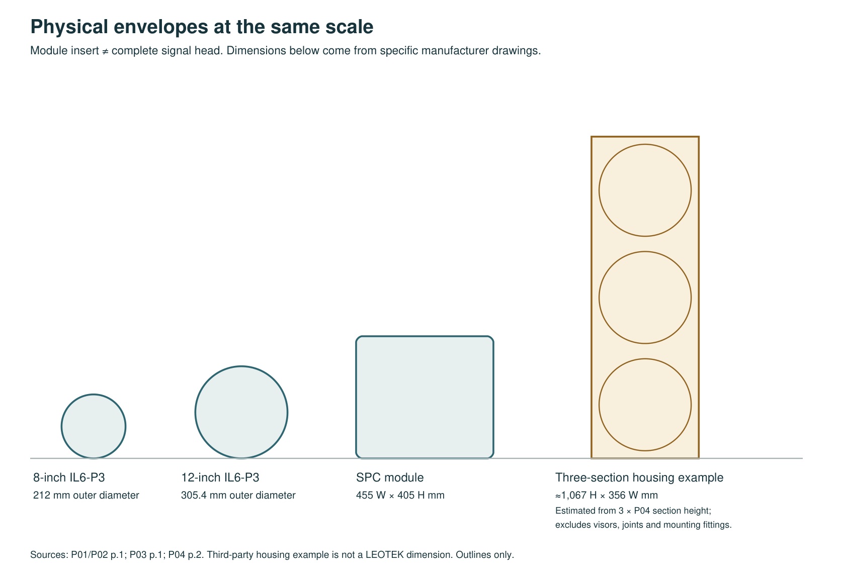
LEOTEK's IL6-P3 drawings show why the size label needs a second check. The 8-inch module has a 212-mm outside diameter, while the 12-inch module has a 305.4-mm outside diameter. The drawings give overall depths of 111.3 mm and 157.2 mm respectively, alongside smaller body-depth dimensions. These are module dimensions, not the dimensions of a complete signal head with its visor and mounting hardware. (LEOTEK IL6-P3 10-28 Vdc specification; LEOTEK IL6-P3 80-135 Vac specification)
Check the drawing against the door opening, retaining arrangement, available rear clearance and wiring route. A module advertised for the right nominal size can still need a different interface. A front-view photograph cannot resolve that question.
| Module | Outside diameter (mm) | Body depth (mm) | Drawing overall depth (mm) |
|---|---|---|---|
| IL6-P3 8-inch circular | 212 | 68.5 | 111.3 |
| IL6-P3 12-inch circular | 305.4 | 107.1 | 157.2 |
Dimensions transcribed from the reviewed IL6-P3 drawings; units are millimetres.
Source: LEOTEK IL6-P3 AC and DC sheets, page 1. Original source 1, Original source 2
Module inserts only. These are not complete signal-head, visor or bracket dimensions. Nominal diameter does not establish a permitted application.
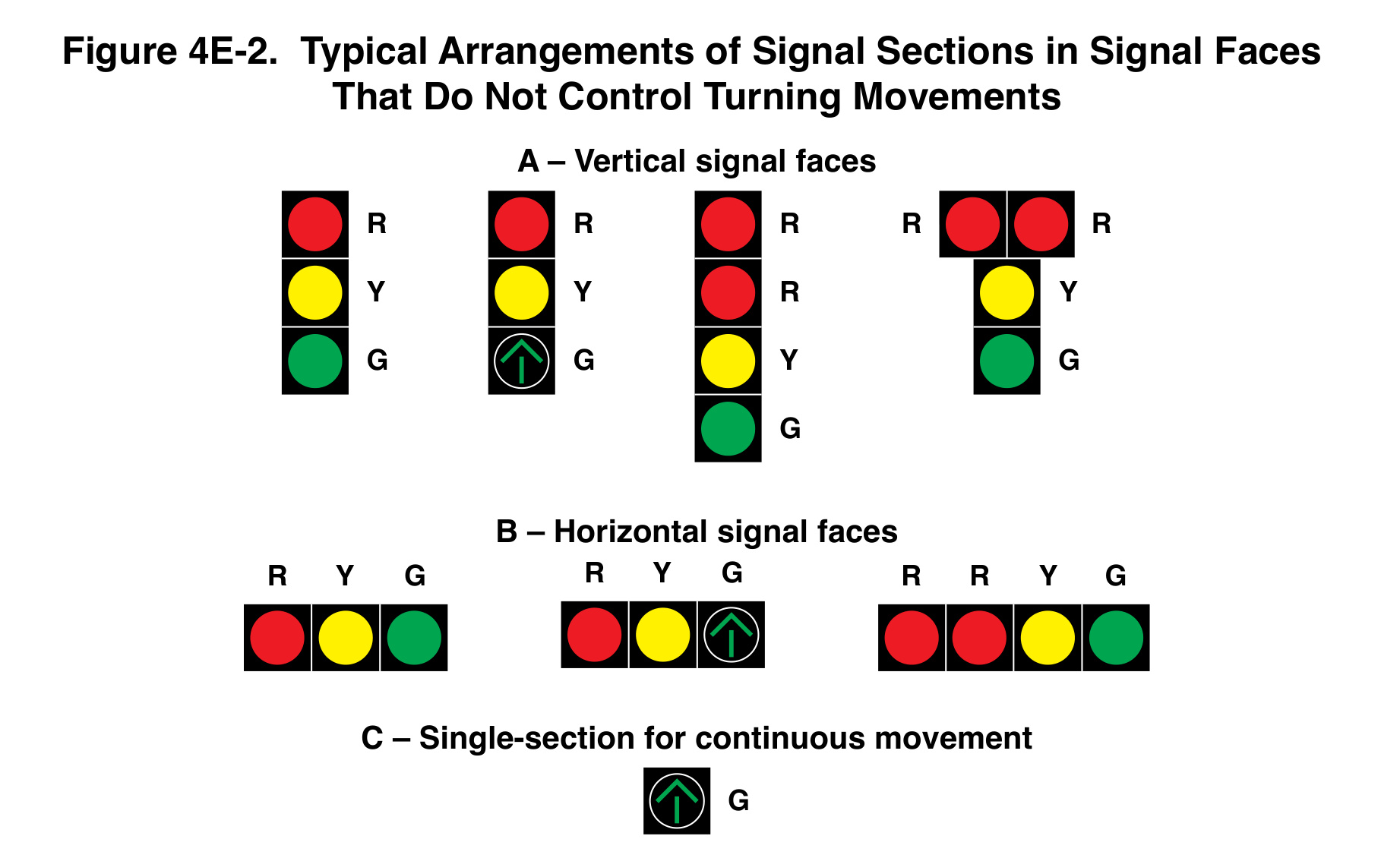
The vertical and horizontal examples preserve the relative positions of the red, yellow and green indications while using different face arrangements. The single-section example has a separate continuous-movement application. These are arrangement illustrations, so their apparent proportions should not be used to select an 8-inch or 12-inch module. Establish the required indication size under Section 4E.02, then verify the offered module and complete housing dimensions separately.
Keep the electrical comparison separate
Within the IL6-P3 ball family, the manufacturer publishes separate AC and DC sheets. An 80-135 Vac module and a 10-28 Vdc module are not substitutes simply because both have a 12-inch face. Color and lens options also belong in the order-code comparison. (LEOTEK IL6-P3 10-28 Vdc specification; LEOTEK IL6-P3 80-135 Vac specification)
Once the application and fit are settled, compare the required optical records, voltage range, monitoring interface and power for the offered configuration. Diameter does not replace those checks. For a retrofit, the useful comparison is the complete proposed replacement against the existing assembly and cabinet conditions, not one isolated catalog dimension.
Questions to resolve before an order
Write down five answers: whether the work creates a new signal face; which provision supports the indication size; which drawing establishes fit; which supply and interface the cabinet requires; and which records support the offered order code. Each answer closes a different question. A single 'compliant' label cannot close all five.
The diameter comparison hides an area comparison
At the same viewing distance, a 12-inch circular face has 1.5 times the diameter of an eight-inch face, but 2.25 times its geometric area: area is proportional to diameter squared. This is calculated geometry using nominal diameters. It is not a claim that the larger module produces 2.25 times the intensity, consumes 2.25 times the power, or delivers a quantified safety improvement. Those outcomes depend on different evidence.
That distinction explains a common mistake in product discussions. A visibly larger luminous area, the brightness of that area, and the intensity sent in a particular direction are related optical considerations, but they are not one catalog field. A comparison that scales a wattage or candela value by face area is making an assumption that needs separate justification.
Apparent angular size also decreases with distance. For a small angle, angular diameter in radians is approximately physical diameter divided by viewing distance, using the same units. Doubling viewing distance approximately halves angular diameter. This geometry helps explain why distance belongs in the application discussion. It does not replace the specific provisions of MUTCD Section 4E.02 or establish a designer's own alternative visibility threshold.
A module drawing and a signal-head drawing solve different fit problems
The dimension diagram above separates inserts from the complete assembly. A nominal 12-inch indication is not a head that is only 12 inches tall. The enclosure, visor, connectors, section joints and mounting hardware occupy additional space. The three-section outline is explicitly an estimate from a separate manufacturer's housing example; it is not a LEOTEK complete-head dimensional drawing.
For a replacement, begin with the insert-to-door interface and the available internal clearance. For a change to a complete head, the review also needs the assembly and support details. A dimension that establishes one interface cannot be reused as the complete envelope for another. Tennessee DOT's signal-head and support chapter provides an agency-specific example of treating signal heads and supports within a broader design chapter. Use the project's governing details for the actual installation.
An illustrative purchasing error makes the distinction concrete. A buyer confirms that a replacement has the expected nominal diameter but omits the overall rear depth from the comparison. The electrical housing then interferes with an existing internal feature. The lens size was correct; the incomplete envelope review was not. This is a planning scenario, not a reported LEOTEK defect or an instruction for modifying a housing.
What changes when eight-inch maintenance becomes a redesign?
An inventory can contain eight-inch equipment without answering what a new design should specify. The scope of the proposed work matters. A like-for-like maintenance activity, a newly installed signal face and a changed approach configuration should not be collapsed into a single purchasing rule. The responsible agency must determine the governing design basis for the work.
The national manual's listed exceptions are bounded. If an exception combines location, speed and distance conditions, keeping only the convenient condition changes the rule. A useful review note identifies the exact provision, the relevant project facts, and the resulting design decision. It should not simply say that the existing hardware was eight inches. MUTCD Section 4E.02 is the primary national reference for the indication-size discussion in this article.
Compare the options without inventing a universal winner
Once the application is resolved, place physical fit, electrical variant, required optical performance and the agency's acceptance evidence in separate rows. The larger nominal diameter does not select the voltage, and the correct voltage does not establish the optical configuration. A precise comparison can reveal that a proposed replacement solves three rows while leaving the fourth unresolved.
For a supplier discussion, send the existing head identification, the relevant drawing or measured clearance information collected by qualified personnel, the required indication and input supply, and the project's design requirement. Ask for the matching order code and configuration-specific records. That gives the supplier enough context to answer a real fit and performance question, while keeping the agency responsible for the application decision. The payoff is fewer ambiguous substitutions rather than a claim that any one diameter or family is suitable everywhere.
What a larger indication does not fix
Changing diameter is only one intervention. A signal can remain difficult to interpret because another vehicle blocks the view, the approach alignment places the driver away from the intended viewing direction, or the background competes with the indication. Those problems need an approach review. Ordering a larger insert before identifying the limiting condition risks paying for a change that leaves the original issue unresolved.
For a design discussion, compare two sketches of the same approach. Keep the driver positions and obstructions fixed, then show the proposed face and its mounting. Record what improves, what remains blocked, and which other design decisions are affected. The sketch is an investigation aid, not proof of compliance. Use the applicable MUTCD Section 4E.02 provisions and the agency's design requirements to determine the acceptable installation.
Compare the installation as well as the indication size
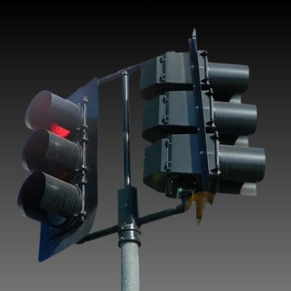
The handbook shows a mast-arm installation and a span-wire installation. These are different support arrangements, not a controlled comparison of 8-inch and 12-inch modules. They put the nominal lens diameter back into the context of a complete signal head and its location over the approach.
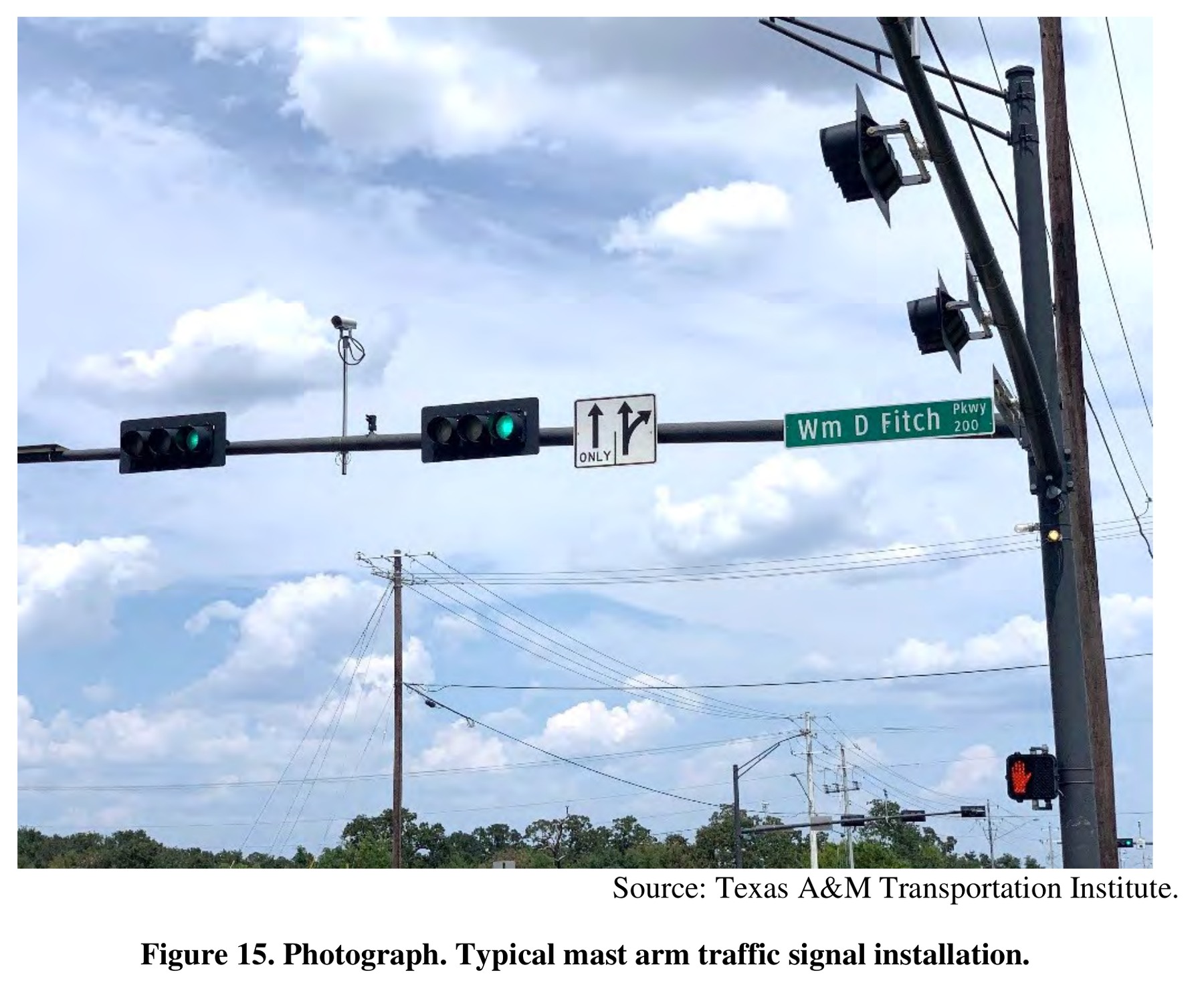
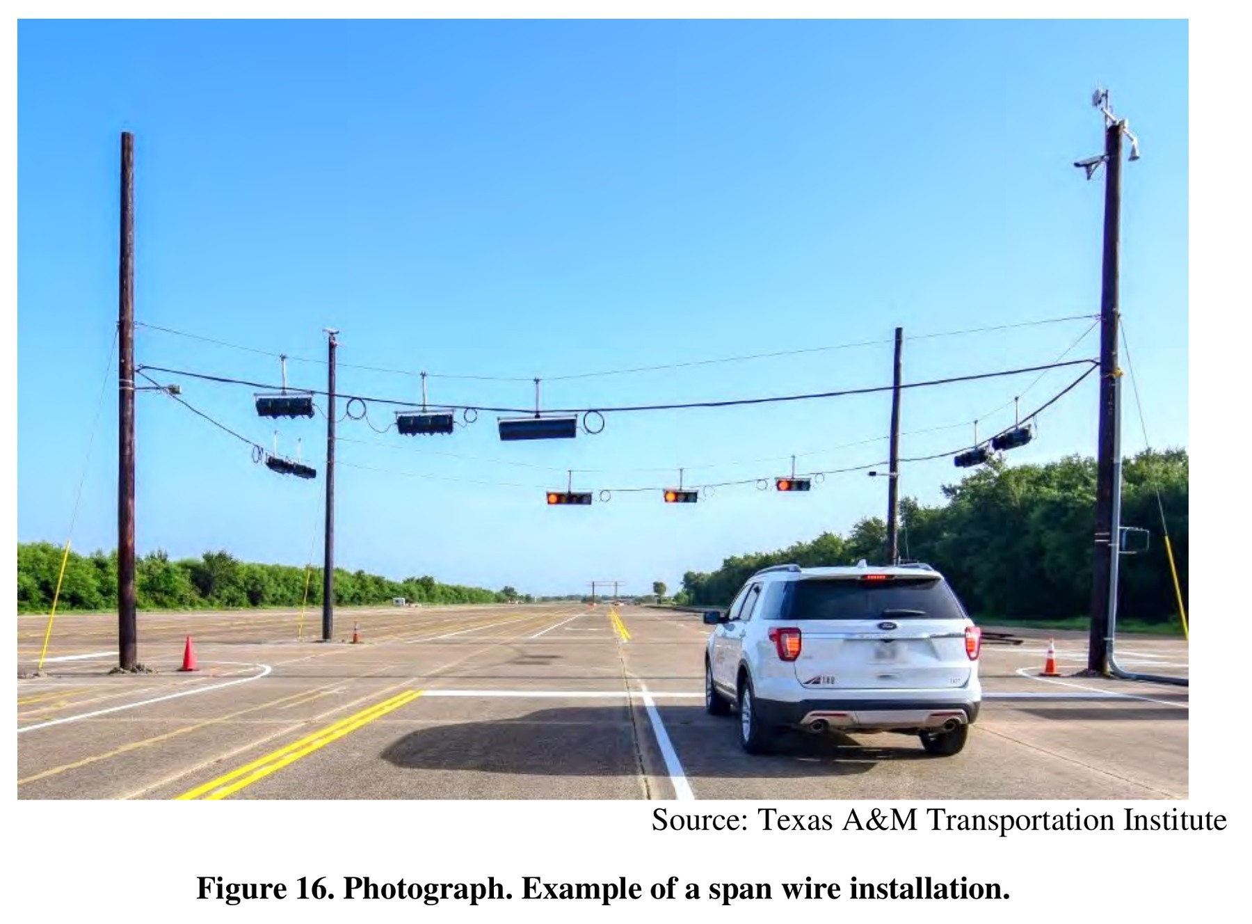
These reference photographs explain general installation arrangements. Inclusion does not imply endorsement, approval or certification of LEOTEK or any specific product by FHWA or Texas A&M Transportation Institute.
A larger indication does not correct a head aimed away from the relevant driver, an obstructed sight line or an unsuitable support arrangement. Review the mounting position, aiming, stability and assembly envelope with the actual project drawings.
Perspective in these photographs cannot establish lens diameter, mounting height or structural capacity. Use the manufacturer’s dimensioned drawings and the project’s structural and placement review for those checks; do not scale an order from a reference photograph.
Follow the change through the assembly and the budget
An illustrative retrofit estimate might include a module, a compatible housing, mounting hardware, installation access and traffic control. A quote limited to the module can therefore understate the cost of moving from one face size to another. The supporting structure and attachment also need the responsible designer's review where affected; the nominal diameter is not a structural calculation.
Separate reusable components from components requiring replacement, and identify who confirmed compatibility. A vendor statement about an insert fitting a housing does not settle the suitability of an entire installed support. Tennessee DOT's signal-head and support chapter is an agency-specific reference for the broader supports-and-heads design context, rather than a national approval of a particular retrofit.
Maintenance then needs the final assembly identification. If the project changes some heads but retains others, record the locations and spare requirements for both. A mixed fleet can be manageable when the inventory is explicit. It becomes troublesome when a purchase order says only LED signal upgrade and the crew must discover which size and electrical configuration each location requires. The selection is complete when design, delivery and maintenance records all describe the same installed equipment.
Frequently asked questions
Are 12-inch traffic signals required everywhere?
Section 4E.02 requires them for all arrow indications and, subject to listed exceptions, circular indications in new signal faces. That wording should not be rewritten as a universal instruction to replace every existing 8-inch indication. (MUTCD Section 4E.02)
Can an 8-inch module be replaced with a 12-inch module in the same head?
Do not assume so. Compare the complete module drawing with the door, retainer and rear clearance. The reviewed IL6-P3 drawings show different outside diameters and overall depths for the two sizes. (LEOTEK IL6-P3 10-28 Vdc specification; LEOTEK IL6-P3 80-135 Vac specification)
Does a larger indication prove better optical compliance?
No. Size establishes one design attribute. Required luminous-intensity, color and other optical evidence still needs to match the offered module and the specification being used.
Sources
- MUTCD Section 4E.02. 11th Edition with Revision 1, PDF page 718 / printed page 677
- LEOTEK IL6-P3 10-28 Vdc specification. Revision July 1, 2019; drawing page 1, model table page 2
- LEOTEK IL6-P3 80-135 Vac specification. Revision December 12, 2018; drawing page 1, model table page 2
Additional research and calculation basis
- MUTCD Section 4E.02, indication sizes
- Tennessee DOT, Traffic Design Manual, Chapter 6: Supports and Signal Heads; agency-specific example
Cover image: AI-generated editorial illustration for LEOTEK. The generic scene is not a verified installation, product photograph or test record. Technical figures and tables carry their own source credits.