




A pedestrian hybrid beacon (PHB) and a rectangular rapid flashing beacon (RRFB) can both make a crossing more conspicuous, but they ask drivers to do different things. An RRFB supplements a crossing warning sign. A PHB provides a red indication that stops traffic during the pedestrian walk interval. That difference should lead the selection discussion before appearance, power supply or purchase price.
The right starting point is the crossing problem: available gaps, vehicle speeds, crossing length, visibility and the people who need to cross. The current MUTCD treats PHBs in Chapter 4J and RRFBs in Chapter 4L. Their provisions are not two versions of a single pedestrian signal warrant.
What is a pedestrian hybrid beacon, also called a HAWK?
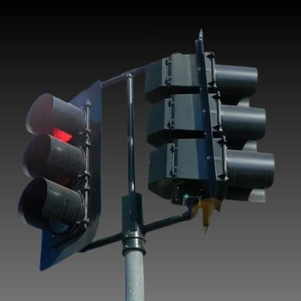
A PHB is a traffic control device used at a marked crosswalk to warn and control vehicle traffic for pedestrians. HAWK, often expanded as High-Intensity Activated crossWalK, is a name readers may encounter for this treatment. The current Manual on Uniform Traffic Control Devices uses pedestrian hybrid beacon. The beacon head consists of three sections: two red indications above a single yellow lens, centered between the red sections.
The Federal Highway Administration describes applications on higher-speed roadways at midblock crossings and uncontrolled intersections. That description is an introduction to the treatment, not a blanket rule for every road with three or more lanes. Chapter 4J’s study and design provisions still determine the appropriate application.
Decide what the crossing needs drivers to do
At an uncontrolled marked crosswalk, an RRFB adds a conspicuous yellow warning when activated. It does not introduce a red stop phase or a pedestrian WALK interval. Pedestrians still need to establish that traffic has yielded or stopped as appropriate before crossing. The required pushbutton sign, when pushbuttons are used, tells users to wait for a gap in traffic.
A PHB changes the operating sequence. It normally remains dark, then serves pedestrian demand through yellow and red indications. Pedestrian signal heads tell users when to begin crossing. Both devices need an appropriate site design; neither corrects a hidden approach, inaccessible landing or poorly located crosswalk merely by flashing more brightly.
| Design question | PHB | RRFB |
|---|---|---|
| Driver indication | Yellow sequence, steady red, then alternating flashing red | Rapidly flashing yellow warning |
| Pedestrian information | Pedestrian signal heads; WALK and clearance intervals | No WALK interval created by the RRFB |
| Primary application reference | MUTCD Chapter 4J | MUTCD Chapter 4L |
| Study focus | Need for controlled crossing, volumes, speed, length and gaps | Eligible uncontrolled marked crossing and warning treatment suitability |
Use the table as an orientation, not a purchasing specification. A project still needs the complete sign, marking, detection, accessibility, timing and placement provisions for the selected treatment. The responsible agency’s adopted requirements and site-specific engineering study govern the design.
Read the PHB graphs with crossing length in view
Section 4J.01 permits consideration of a PHB where traffic signal warrants are not met, or where pedestrian or school-crossing warrants are met but a decision is made not to install a traffic control signal. The study considers major-street volumes, speeds, widths and gaps together with pedestrian volumes, walking speeds and delay.
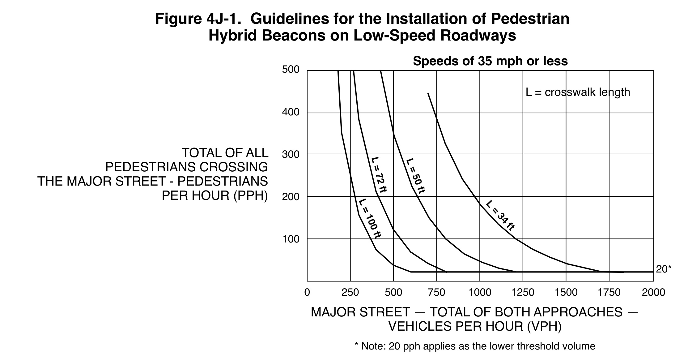
Figure 4J-1 applies where the posted or statutory speed limit, or the 85th-percentile speed, is 35 mph or less. Its horizontal axis combines major-street traffic from both approaches. Its vertical axis is the corresponding total pedestrian crossings during one hour of an average day, comprising four consecutive 15-minute periods. The curves distinguish crosswalk lengths.
A longer crossing changes the gap a pedestrian needs. That is why two sites with identical vehicle and pedestrian counts can fall differently relative to the applicable curves. Measure the crossing being evaluated rather than substituting roadway right-of-way width or assuming all four-lane roads have the same pedestrian travel distance.
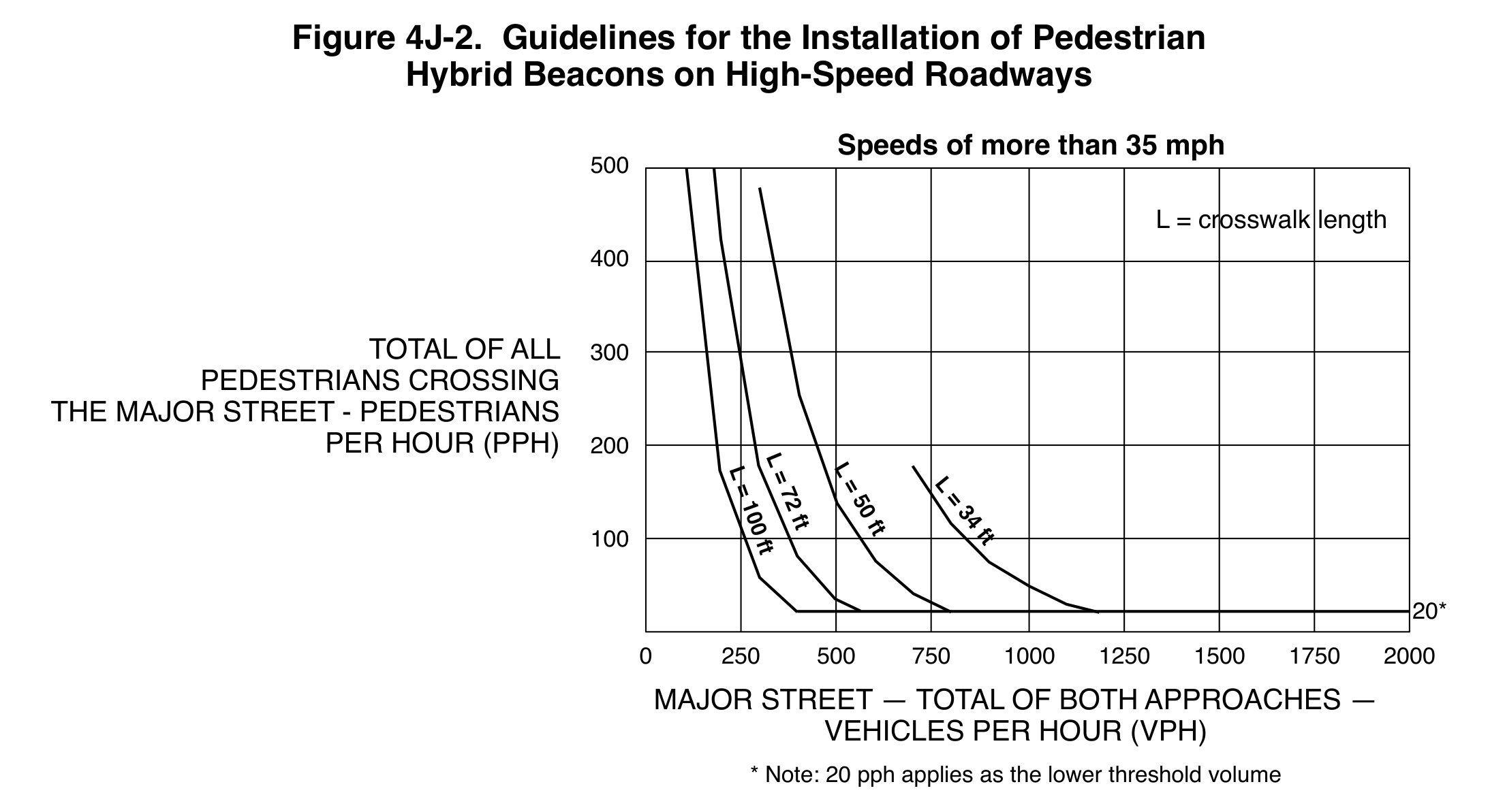
Figure 4J-2 applies when the specified speed measure exceeds 35 mph. Both figures have a 20-pedestrian-per-hour lower threshold, but that floor is not a universal installation trigger. The corresponding vehicle volume and applicable length curve remain part of the guidance. Values for other crossing lengths should be interpolated between the published curves.
The manual also permits a pedestrian-volume reduction of as much as 50 percent when the 15th-percentile crossing speed is below 3.5 feet per second. A sufficient median waiting area can support separate consideration of each traffic direction. Document these assumptions: selecting a curve is an engineering decision about the actual crossing, not a way to make the plotted point look favorable.
The PHB sequence explains the operating difference
In ordinary operation, the lenses remain dark until activated by a pedestrian. A person can use a call button to activate the beacon. A coordinated installation or a programmed minimum dark time can delay the start after a request; pressing the button does not promise an instant red signal. The approved timing plan defines that response.
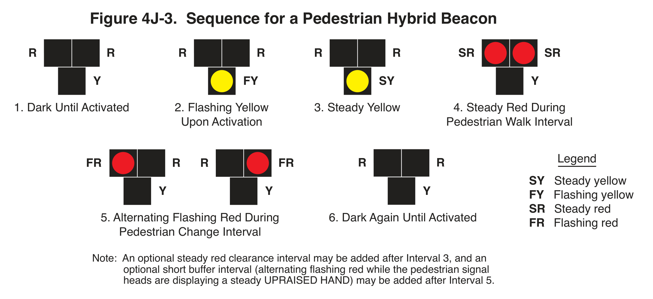
Read Figure 4J-3 from left to right. The PHB is dark between actuations. A pedestrian request initiates flashing yellow, followed by steady yellow, then both red indications steadily illuminated during the pedestrian walk interval. Alternating flashing red accompanies the pedestrian change interval, after which the beacon returns to dark, subject to the manual’s permitted interval options.
Drivers must stop at flashing red, then may proceed when clear under the applicable rules; each following driver must make the required stop. This is different from treating the flashing-red interval as either a continuous steady red or permission to follow the vehicle ahead without stopping. Outreach should explain that distinction with the actual sequence.
The pedestrian display follows a related but separate sequence. In the ordinary operation described in Section 4J.03, the WALKING PERSON appears with steady red for drivers, and the flashing UPRAISED HAND appears with alternating flashing red. A yellow beacon indication is not an invitation for a pedestrian to start crossing. The figure is an operating reference, not a fixed timing plan.
Plan the PHB as a complete crossing installation
A PHB face has one circular yellow indication centered below two horizontally aligned circular red indications. Section 4J.02 requires at least two PHB faces for each major-street approach, stop lines, pedestrian signal heads at both ends of the marked crosswalk and pedestrian actuation. If installed at or immediately adjacent to an intersection, the minor approaches require STOP signs.
Placement guidance becomes particularly relevant above 35 mph or where roadside faces would be obscured: both minimum faces should be overhead in those circumstances. On multilane approaches at 35 mph or below, the manual provides roadside/median and overhead guidance. These distinctions affect supports, power, sight lines and construction scope before equipment is ordered.
The design review should include parked vehicles and other sight obstructions, accessible routes and information, drainage at the waiting area, detector reach and the intended maintenance access. Chapter 4J points to accessible pedestrian signals for information in nonvisual formats. A visible WALK symbol alone does not serve every user.
Where an RRFB fits, and where it does not
Chapter 4L permits RRFBs to supplement pedestrian, school or trail crossing warning signs at marked crosswalks across uncontrolled approaches. An RRFB cannot simply be added to any crossing that feels difficult. The permitted sign types, mounting arrangement and existing traffic control are part of its application.
The current provision prohibits RRFB use across approaches controlled by YIELD signs, STOP signs, traffic signals or PHBs, with specified exceptions for roundabout approaches or exits and free-flow turn lanes separated by a channelizing island. Identify the exact approach being crossed; a STOP sign on a different leg does not by itself describe the control on that crossing.
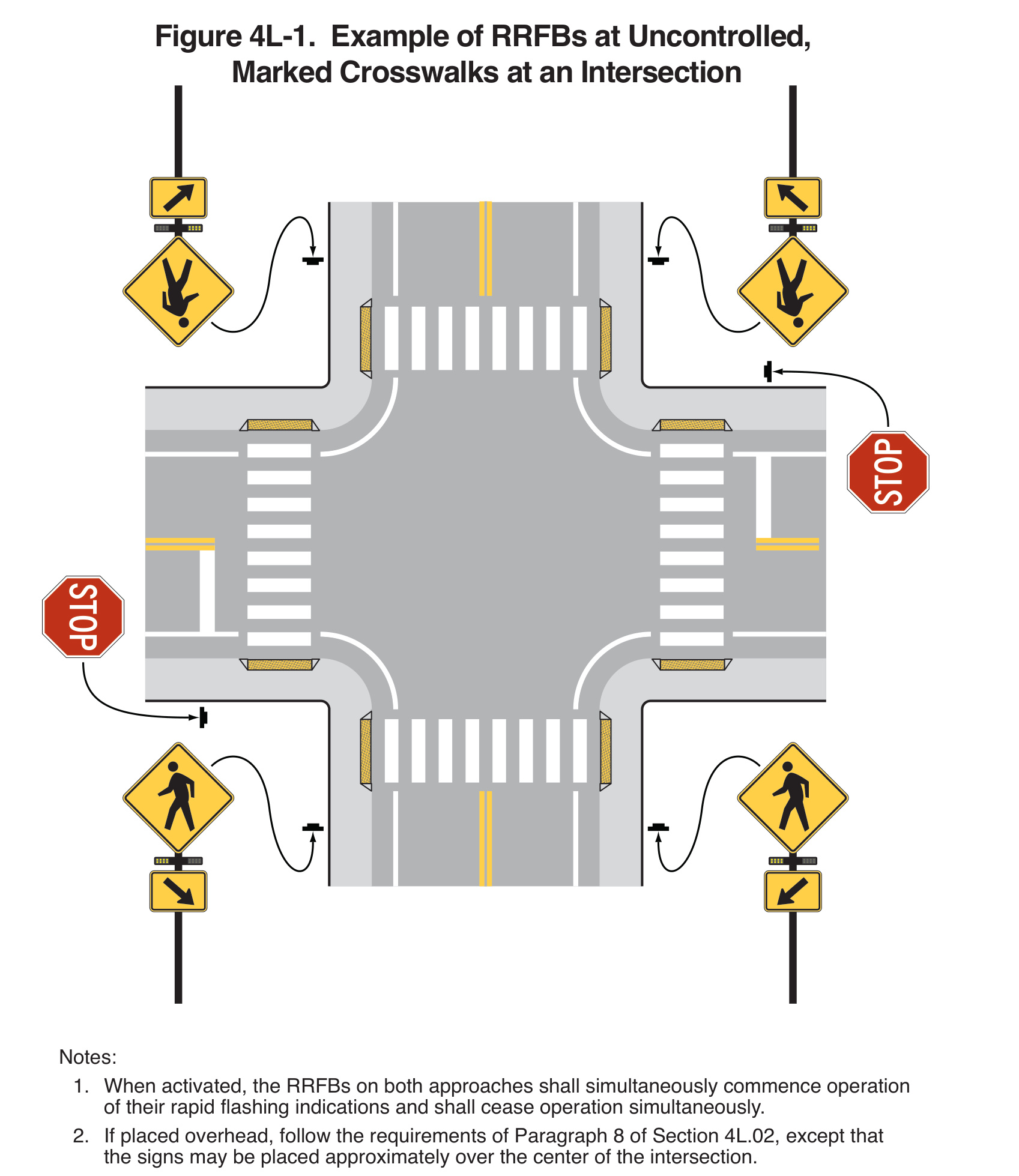
Figure 4L-1 makes that distinction visible. The side-street STOP control is separate from the uncontrolled major-street crosswalks served by RRFBs. The arrows indicate the directions faced by the assemblies. The figure also shows why an installation plan must define which units operate together, rather than treating each roadside beacon as an independent device.
For post-mounted signs, at least two crossing-sign assemblies with RRFB units and downward-arrow plaques are required at the crosswalk, one on each side of the roadway for the approach. The current chapter also provides an overhead alternative. The illustration is one permitted arrangement, not the only layout an engineer can design under the chapter.
Activation, nighttime visibility and maintenance affect the result
RRFBs are normally dark and operate on pedestrian actuation. All units associated with a given crosswalk start and stop together. With a predetermined flash period, each new detection must initiate that period, including a detection while the beacons are already flashing or immediately after they stop. A short demonstration with one push does not test this behavior.
Section 4L.03 ties guidance for the minimum operating period to pedestrian clearance-time procedures and notes the time needed to confirm yielding. Section 4L.02 also recommends an audible information device for people with vision disabilities. Verify those functions in the submittal and field commissioning, rather than assuming a button and yellow lamps describe the complete system.
Daytime conspicuity and nighttime glare deserve separate checks. The chapter specifies daytime intensity criteria and permits automatic dimming if the indications cause excessive glare at night. Review from realistic driver and pedestrian positions. A close photograph of an illuminated beacon cannot demonstrate how clearly the person waiting at the curb is seen.
Use research without turning it into a guarantee
FHWA identifies both PHBs and RRFBs as proven safety countermeasures. Its summaries are useful entry points to the research, but the current MUTCD remains the application reference. A reported driver-yielding rate is an observed behavior measure, not the same outcome as crash reduction, and it is not a guaranteed result for another site.
When evaluating a study, keep its treatment, comparison method, road configuration, speeds and pedestrian conditions attached to the finding. The MUTCD figures reproduced here are guideline curves and an operating/layout illustration. They are not experimental measurements of a LEOTEK product. Their value is in clarifying the design decision, not proving a manufacturer’s safety claim.
Write the project brief before the equipment list
State the crossing problem, measured conditions, alternatives considered, selected control and remaining design questions. Include a plan showing signs, faces, stop lines where applicable, detection, pedestrian facilities and clear sight lines. Then identify who owns timing, commissioning, public education and ongoing inspection.
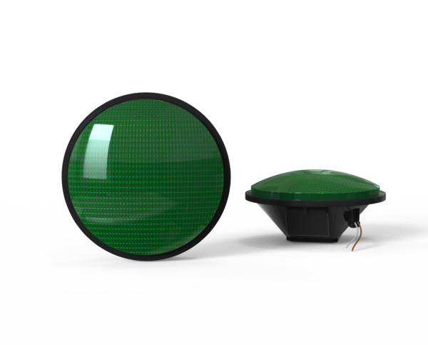
A module supplier’s electrical and optical documents support equipment selection within that design. They do not establish that a complete PHB or RRFB system is being supplied. Keep the boundaries clear in the request for quotation: modules, heads, supports, controller, detectors, power and installation may have different responsible parties.
Frequently asked questions
Is an RRFB a smaller pedestrian traffic signal?
No. It is supplemental warning at an eligible marked crossing. It has no red stop phase and does not provide a pedestrian WALK interval. PHBs and conventional signals have different control functions and design provisions.
Must a crossing meet a full signal warrant before a PHB is considered?
No. Section 4J.01 expressly provides for consideration where traffic signal warrants are not met, as well as certain pedestrian/school-warrant situations where a signal is not selected. An engineering study still evaluates the crossing and the PHB guidance.
Does 20 pedestrians per hour automatically justify a PHB?
No. That is the lower threshold noted on the PHB figures. Major-street vehicle volume, crossing length, the speed-based figure and the rest of the engineering study remain necessary to interpret the point.
Can an RRFB replace required signs or pedestrian accessibility features?
No. It supplements specified crossing warning signs. The complete design must address placement, detection and accessible information under the applicable provisions. Procurement should identify those functions explicitly rather than treating them as optional accessories.
What should a motorist do at a pedestrian hybrid beacon?
Recognize the entire yellow to red lighting sequence. Flashing yellow warns of activation; steady yellow indicates the transition to red. Come to a stop for the steady red signal indication. During alternating flashing red, each driver stops and then proceeds only when permitted and the path is clear under the applicable rules. Do not follow another vehicle through without the required stop or enter an occupied conflict area.
When should pedestrians enter the crosswalk?
Use the pedestrian display, not the yellow signal facing drivers, to decide when to begin. The WALKING PERSON normally appears during steady red for vehicles. The flashing hand, sometimes called flashing don’t walk, is the pedestrian change interval for completing a crossing already started. Check that traffic has stopped as required before entering and remain alert to turning or noncompliant vehicles.
Does a countdown tell drivers when to move?
No. A pedestrian countdown communicates the remaining pedestrian change interval. The motorist follows the vehicle-facing beacon indications and applicable rules. A countdown does not release traffic or certify that the crosswalk is clear. Pedestrian heads, timing, accessible information and beacon operation need to be reviewed together.
What does a STOP sign on the side street mean for RRFB eligibility?
Identify the approach that the marked crosswalk actually crosses. An RRFB across an uncontrolled major-street approach is different from one across an approach controlled by a stop sign. Chapter 4L limits the latter application, with specific roundabout and separated free-flow turn-lane exceptions. The sign on a different leg is not enough information to determine eligibility.
How does the beacon help people cross the street?
Its lighting sequence moves from warning to stop control so pedestrians can use a defined WALK interval to cross the roadway. The PHB is a traffic control device designed for a marked crossing; flashing and steady lights communicate distinct instructions. A red phase is used to stop conflicting traffic and allow pedestrians to cross. The beacon displays do not remove the need to observe vehicles and pedestrians in the crosswalk.
How should an agency explain activation to the public?
Explain where a pedestrian desiring to cross can request service, what confirms the request and when the WALK display appears. A call-button request initiates a yellow to red sequence under the approved controller plan. The initial warning directs motorists to slow, while the later steady red requires a stop. Use the actual site sequence in education, rather than suggesting the pedestrian can immediately begin to safely cross.
Can a crash-reduction percentage be promised for this crossing?
No. Research on pedestrian crashes can inform the treatment decision, but a study estimate is tied to its sites, methods and outcome definition. It does not guarantee this site’s future performance. A motorist yielding rate and a pedestrian crash reduction measure answer different questions. Record the study conditions and evaluate the crossing after implementation.
Conclusion: select the control before the equipment
A pedestrian hybrid beacon provides a controlled pedestrian crossing phase; an RRFB provides supplemental warning. Record the actual crossing length, corresponding counts, speed measure, sight lines and accessibility needs before choosing between them. Then commission the complete operating sequence, including repeated requests, nighttime operation and the information each user receives.
Further reading and technical sources
- FHWA, MUTCD 11th Edition with Revision 1, Chapter 4J, printed pp. 727-730; Figures 4J-1, 4J-2 and 4J-3. Section 4A.04: meanings of flashing red indications.
- Chapter 4L, printed pp. 736-739; Figure 4L-1. Application and overhead-placement provisions include Revision 1 changes.
- FHWA, Pedestrian Hybrid Beacons, FHWA-SA-21-045; research summary and references.
- FHWA, Rectangular Rapid Flashing Beacons, FHWA-SA-21-053; research summary and references. Current federal manual checked October 18, 2026; confirm agency-specific requirements.
Continue the crossing-design review
- Traffic Signal Warrants: Read the Four-Hour and Peak-Hour Curves Correctly
- When Does a Pedestrian Crossing Need a Signal? Reading the MUTCD Volume Warrants
Cover: AI-generated editorial illustration for LEOTEK, not a verified installation or product photograph. Technical figures: FHWA/MUTCD originals, individually credited above.
Review the modules within the approved crossing design
Once the agency defines the crossing treatment, compare the required indications and electrical configuration with the IL6-P3 signal-module family and SPC pedestrian-module options. Those module families are not a representation that LEOTEK supplies the entire PHB or RRFB installation. Send the application, voltage and supporting-document questions to LEOTEK for a configuration-specific review.