




IES light distribution types describe the directional character of a luminaire’s light output. Type I is narrow and two-sided; Types II and III suit different degrees of side-mounted lateral reach; Type IV is forward-biased; Type V has circular symmetry, and Type VS has square symmetry. Use these labels to shortlist optics, then verify the exact IES file in a project photometric calculation.
A distribution label is useful at the start of a lighting discussion. It becomes risky when it is treated as the finished design. Two fixtures can carry the same label and still produce different dark spots, boundary spill and usable pole spacing. This guide explains what each type means, where it can be useful and what to check before specifying it.
IES light distribution Types I, II, III, IV, V and VS
The familiar sketches are a visual shorthand. Formal lateral classification uses the luminaire’s intensity distribution and mounting-height reference geometry, rather than the outline of a patch photographed on pavement. The Iowa SUDAS Design Manual, Section 11B-1, provides a public explanation of the classification. Older literature often uses “IESNA”; the organization is now generally identified as IES, the Illuminating Engineering Society.
How to read these diagrams: the dark dot marks the luminaire mounting point in plan view. Amber shows a qualitative directional concept. These original illustrations are not measured candela plots, isolux contours, fixed coverage boundaries or drawings to a shared photometric scale. Backlight and edge performance depend on the actual optic.
Type I: narrow, two-sided distribution
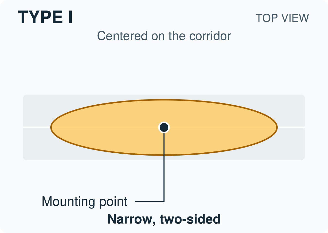
Type I is associated with a narrow corridor and a luminaire positioned near its centerline. Think of a path, median or other linear space where light is needed in two opposing directions. The defining idea is the relationship between the optic and the corridor, rather than a spotlight aimed at an object. A center-mounted sketch does not establish that every existing pole can serve the same layout.
Type II: side-mounted, shallower lateral reach
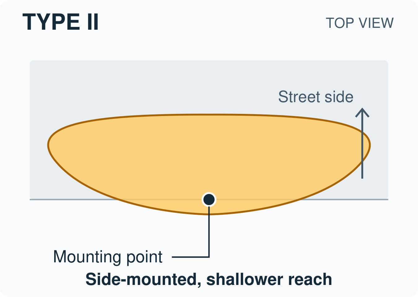
Type II is a common starting point for a relatively narrow roadway lit from the side. Its lateral classification is more contained than Type III. On an existing street, check the far curb and the longitudinal gap between poles separately. A suitable cross-road reach can coexist with a weak midpoint between poles; the type label does not describe every part of the distribution.
Type III: broader reach from the side
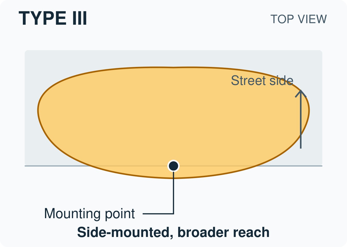
Type III extends the side-mounted concept farther across the target area. It is often considered for wider roadway sections, parking areas or perimeter positions where the optic must reach beyond the near edge. This is a candidate application, not a guarantee of better lighting. Compare the useful light on the far side with the light reaching neighboring windows or areas outside the project boundary.
Type IV: forward-biased distribution
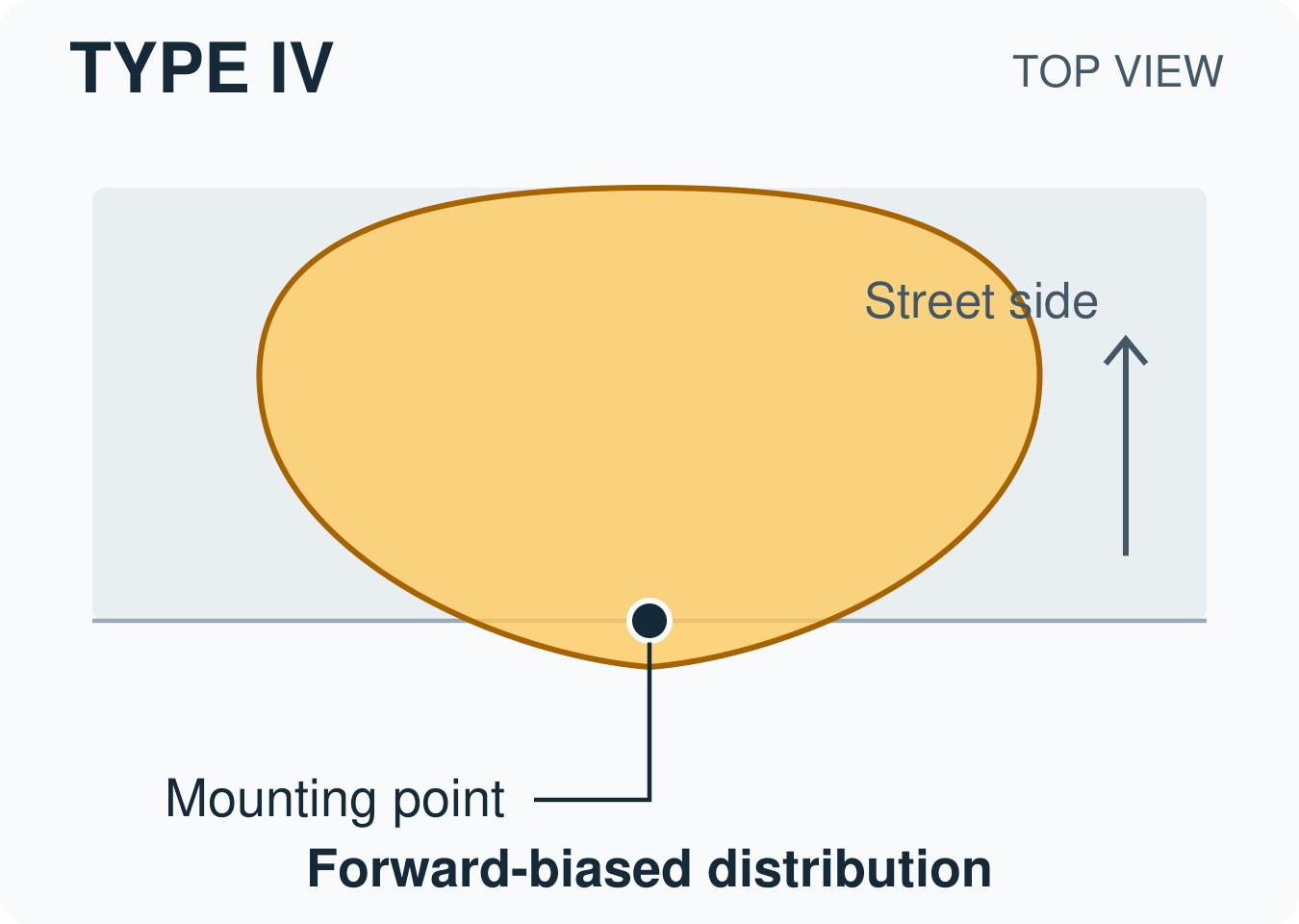
Type IV emphasizes forward reach from a side or perimeter position. It can be useful where the luminaire must push light into an area ahead of the mounting point. It is an asymmetric distribution, not a symmetrical, two-sided pattern. Forward throw also does not mean zero backlight: check the selected optic, any shield and the installed orientation before making a property-line claim.
Type V: circular symmetry
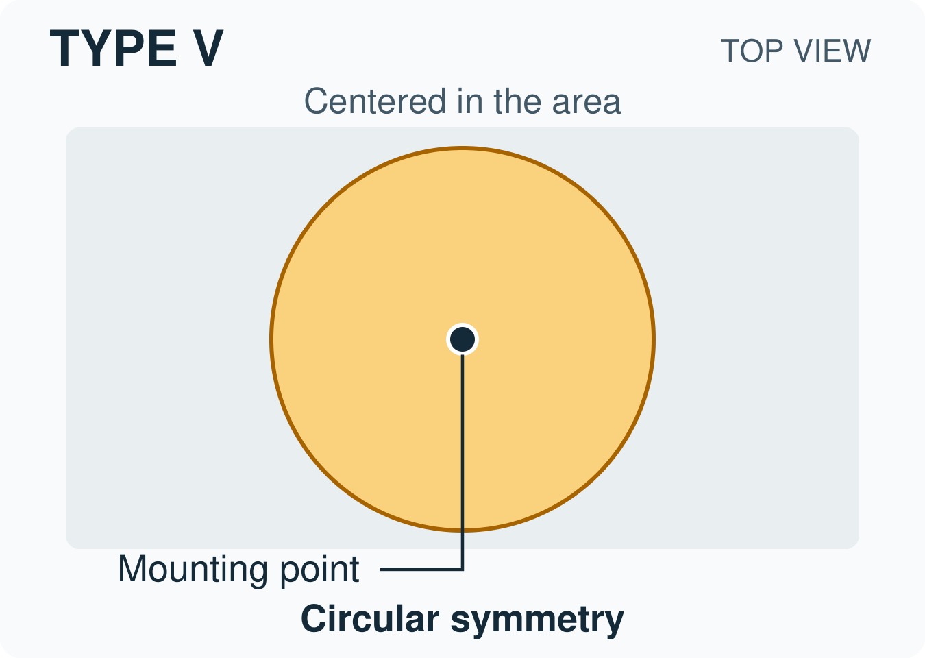
Type V distributes intensity with circular symmetry around the luminaire. It is often considered for interior positions in open areas where light is needed around the pole. Circular symmetry does not mean that every point on the ground receives equal illuminance. Distance, angle, obstructions and overlapping luminaires still shape the result. Nor does Type V automatically make a fixture suitable for sports lighting.
Type VS: square symmetry
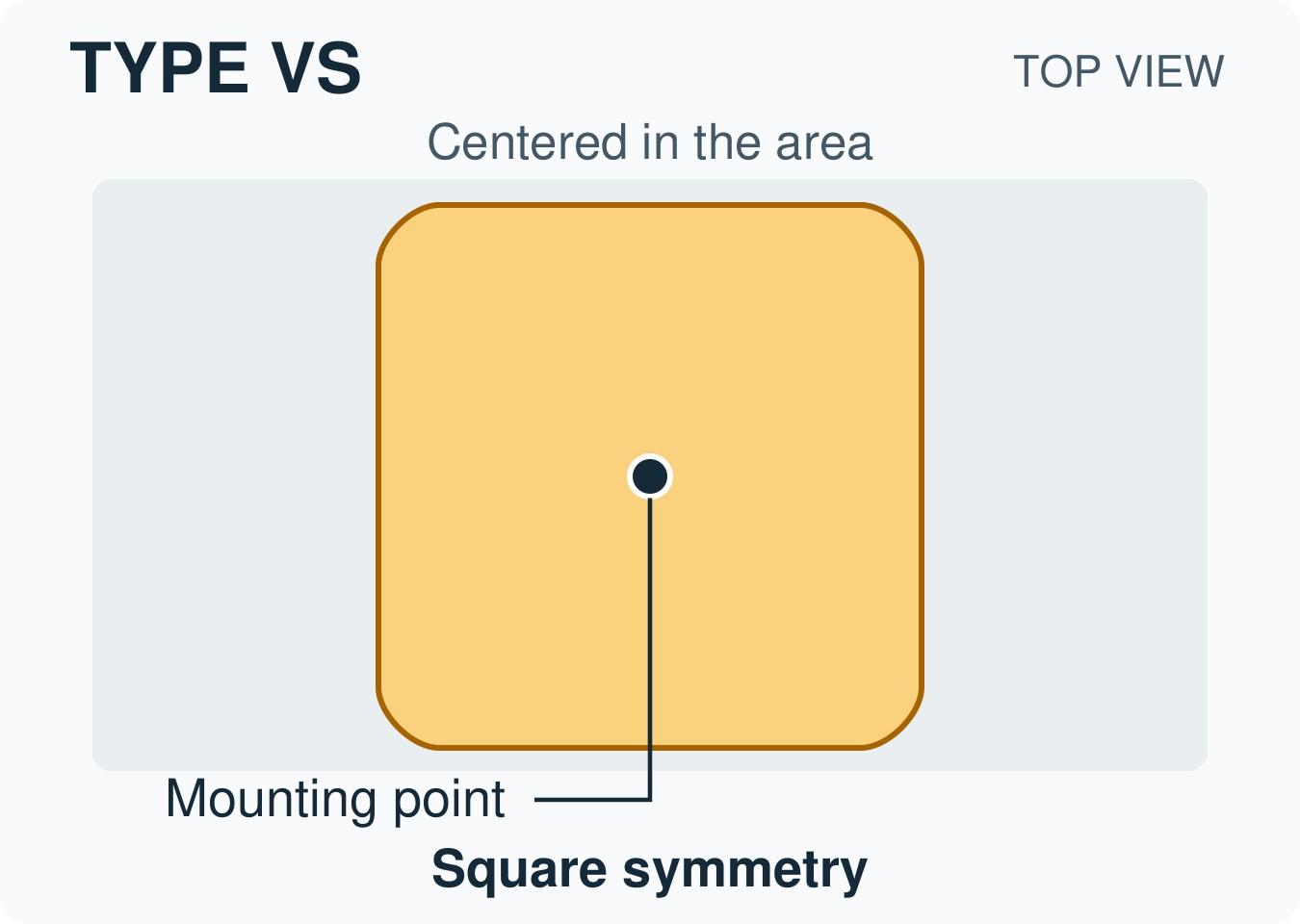
Type VS provides a square-symmetric distribution rather than the circular symmetry of Type V. It can be a useful candidate for a rectangular site organized around a pole grid. The corners of a schematic square are not promised coverage limits. Review the spaces between rows, site boundaries and the orientation of the square pattern in the actual calculation.
Quick comparison: match the mounting position to the task
Use this table to frame the first discussion with the designer or supplier. The examples are starting points for evaluation, not application approvals or substitutes for a lighting calculation.
On smaller screens, swipe the table sideways to compare all columns.
| Type | Starting layout | Question to resolve |
|---|---|---|
| I | Narrow corridor; mounting near center | Does the usable light stay within the corridor? |
| II | Side-mounted, narrower roadway | Are the far curb and between-pole minimums adequate? |
| III | Side-mounted, broader target area | Does extra lateral reach create unwanted spill? |
| IV | Perimeter position with forward reach | What happens behind the optic and at the far boundary? |
| V | Interior pole; light needed around it | Does circular symmetry suit the surrounding layout? |
| VS | Interior grid; square-symmetric pattern | Are corners, row gaps and orientation satisfactory? |
Why mounting-height ratios are not coverage distances
Classification guides describe lateral reference distances in multiples of mounting height, including 1.75 MH and 2.75 MH. The relevant trace is based on half-maximum candela within the classification’s longitudinal range. It is not an illuminance contour at the project’s required light level. At a 30-foot mounting height, 1.75 MH is geometrically 52.5 feet; that arithmetic does not promise adequate illumination 52.5 feet from the pole.
This distinction prevents a costly shortcut: multiplying mounting height by a classification boundary and treating the result as a permitted road width or pole spacing. The site calculation must still account for the actual intensity data, geometry and acceptance criteria.
Type II vs. Type III vs. Type IV: compare the actual weak point
Start with the location that fails the design review. Is it the far traffic lane, the space halfway between poles, a sidewalk behind the luminaire or a residential boundary? “We need a wider optic” is too vague to answer all four.
If the far side is underlit, compare alternative lateral distributions while holding the mounting geometry and calculation criteria constant. If the between-pole minimum is weak, inspect the along-road intensity distribution and overlap as well. Moving from Type II to Type III does not automatically solve an along-road problem. Type IV deserves evaluation when forward reach is the task, but its name alone cannot establish the result.
One particularly useful warning comes from the 2023 FHWA Lighting Handbook, Section 5.3. Its comparison of four Type II luminaires shows substantially different distributions; the discussion also explains why pole spacing cannot simply be transferred between products. Ask for the proposed configuration’s photometry, rather than accepting the old spacing because both fixtures say “Type II.”
Actual photometry: read the curves, not the label
The manufacturer-published examples below put that distinction into practice. All use the VTSSA 72A P11 configuration at 4000K/5000K, 70CRI and a 40-foot mounting height. Each grid interval represents 40 feet. The shared legend lists 0.1, 0.2, 0.5 and 1.0 footcandles; not every panel contains all four contours. These are light-level boundaries, rather than the outline of a distribution class.
T3R and T3F: one broad class, different contours
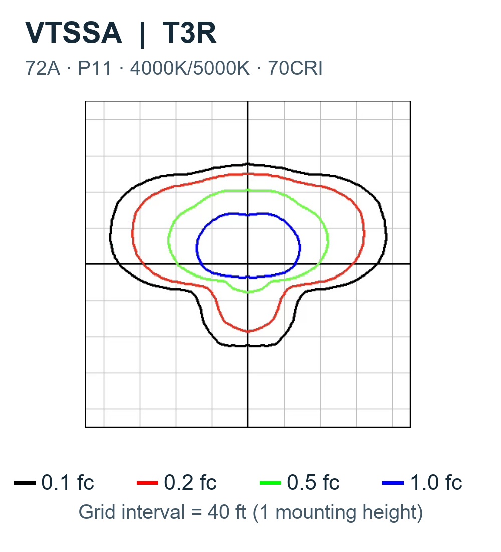
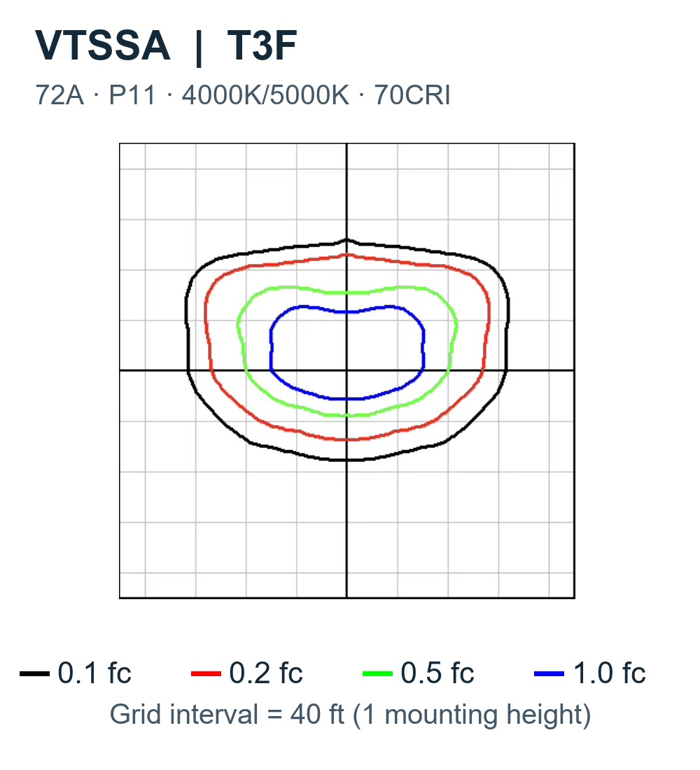
Compare the blue 1.0-footcandle contour first, then follow the black 0.1-footcandle contour. The two optics produce different shapes even though their matching 4000K IES files both identify a Type III optic. Those differences are lost in a generic oval sketch. Neither panel establishes a passing pole layout: multiple-luminaire overlap, maintained-light assumptions and the project’s criteria still need evaluation.
An ordering code can differ from the formal classification
The published optic code “T5” below has a square pattern. Its matching VTSSA-72A-MV-40K7-T5-XX-P11 IES file explicitly describes a Type VS optic. Keep the manufacturer’s ordering code and the distribution classification separate; a “T5” label should not automatically be illustrated with a circle.
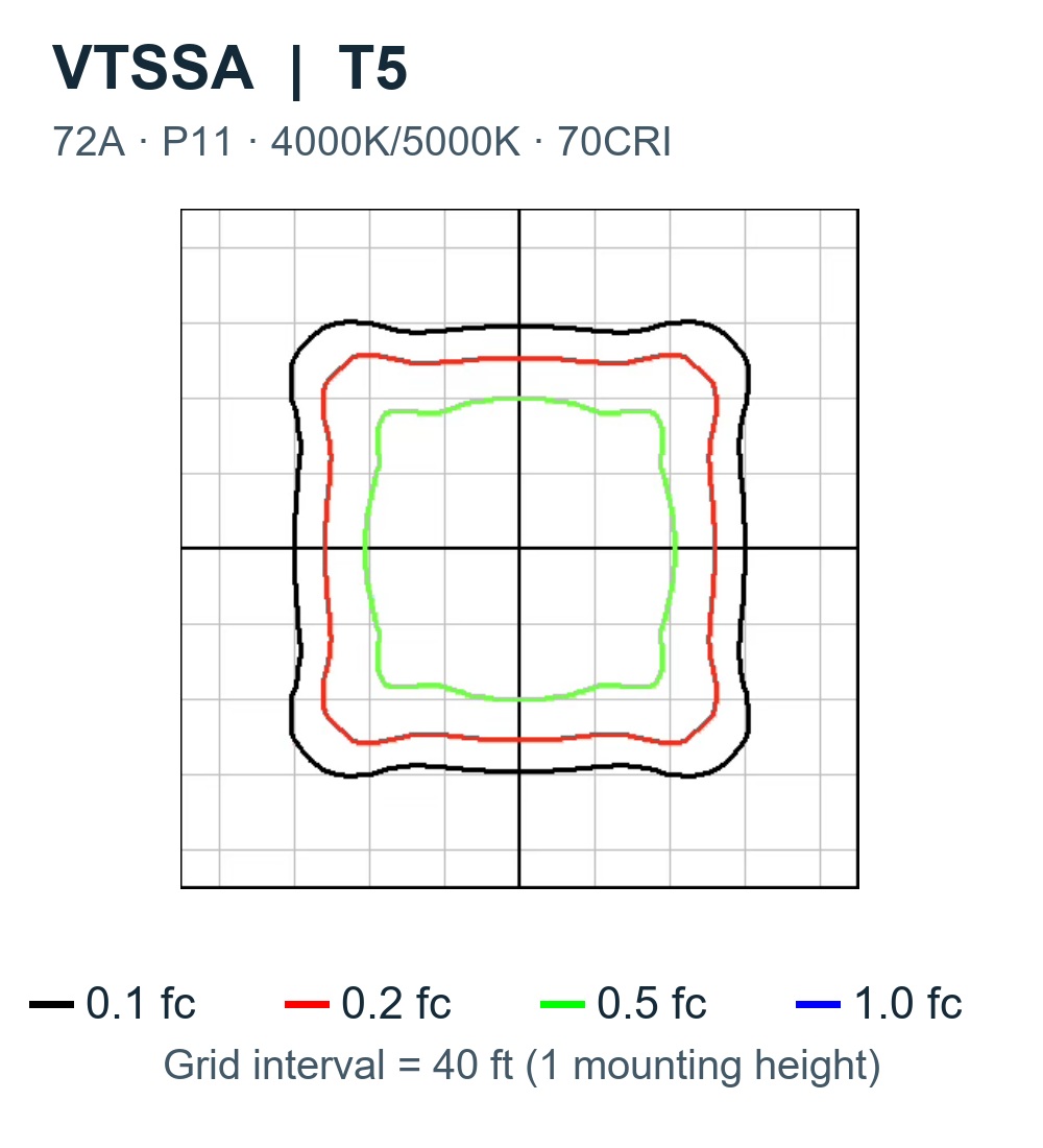
Source boundary: these are configuration-specific plots from the published specification, not universal Type III or Type VS coverage shapes. The supporting IES files are labeled as scaled data. The source plots are reproduced without changing their curves; the six amber sketches above remain introductory concepts.
Distribution type, beam angle, BUG and an IES file answer different questions
Lateral type describes a broad directional class. Short, medium and long describe the longitudinal classification, so the Roman numeral does not tell the whole along-road story. A NEMA floodlight designation describes field-angle spread; it is not a translation of IES Type I–V. In particular, “4H” does not mean roadway Type IV. Lighting Analysts’ photometric report documentation explains the separate beam- and field-angle conventions.
BUG ratings address backlight, uplight and glare-related zonal output. They do not replace a site-specific evaluation of discomfort, disability glare or boundary spill. An IES photometric file contains directional intensity data used by calculation software. Read the IES-file review guide to connect the file, report and order code; use the floodlighting beam-angle guide for that separate selection problem.
A practical photometric review before you specify an optic
1. Establish the geometry and the areas that matter
Record mounting height above the calculation surface, pole positions, arm reach, luminaire tilt and rotation. Include the roadway, sidewalks, crossings, parking aisles and relevant boundaries. Existing poles may be fixed constraints; document them before comparing products. A higher mounting point changes the geometry, but it does not create a universal spacing multiplier.
2. Match the IES file to the proposed configuration
Ask for the exact fixture size, optic code, output setting, CCT and shield arrangement represented by the file. Check how any scaled data relate to the tested configuration. A family brochure and a file with a similar name are not enough to establish a match. Retain the filename, revision and associated submittal together so a later substitution can be reviewed consistently.
3. Agree on the calculation criteria before comparing results
Identify the owner’s applicable criteria, calculation planes, grid and maintained-light assumptions. Keep those inputs consistent across the comparison. A report showing initial values should not be compared casually with one showing maintained values. Confirm whether the task requires illuminance, roadway luminance, vertical illumination or additional glare evaluation. See the roadway uniformity guide for why an average alone is insufficient.
4. Inspect the plan, then investigate the numbers
Locate the minimum points on the drawing instead of reading only the summary box. A minimum at a crossing, a boundary or a gap between poles leads to different design questions. Examine bright spots and neighboring properties too. A visually impressive rendering can conceal an unsuitable calculation boundary; ask which surfaces and locations the reported statistics actually include.
5. Carry the chosen arrangement into procurement and commissioning
Specify the accepted optic, output, shield and orientation with the approved layout. If a substitute is proposed, rerun the relevant calculation instead of relying on an equivalent type label. During commissioning, check installed settings and aim against the design record. Where field measurements are required, document the measurement conditions and compare like-for-like quantities.
Frequently asked questions about IES distribution types
Which IES distribution type is best for a streetlight?
There is no universal best type. Start with the mounting position and target geometry, then compare the exact candidate optics in the same calculation. A narrow road, a wide intersection and a pedestrian crossing can demand different performance even within one corridor.
Can I select Type II or III from road width and pole height alone?
Those dimensions help frame the geometry, but they cannot establish a passing design. Classification references expressed in mounting-height units are not guaranteed illuminated widths. Include setback, spacing, arm reach, tilt, output and the actual intensity data before accepting an optic.
Does Type IV eliminate light behind the fixture?
No. Forward-biased distribution is not a zero-backlight guarantee. Review the exact photometry and available shielding, then evaluate the installed arrangement at the relevant boundary or receiving surface. A shield may also alter useful light, so use data appropriate to that configuration.
What is the difference between Type V and Type VS?
Type V is circularly symmetric; Type VS is square-symmetric. That describes directional organization around the luminaire, not equal illuminance everywhere below it. Pole-grid orientation, spacing and overlap still need review, especially at corners and between rows.
Can two fixtures with the same type use the same pole spacing?
Do not assume so. The type is a broad class, and actual distributions can differ within it. Compare both IES files using the same geometry and criteria. If poles must remain, assess that fixed layout rather than importing a spacing claim from another product.
What information should I send for a useful lighting review?
Send a dimensioned site plan, mounting heights, existing pole locations, target areas, sensitive boundaries and the owner’s criteria. Add the proposed fixture configurations and IES files. State which conditions are fixed and which can change; that makes the comparison actionable.
Sources and technical references
- Iowa SUDAS, Design Manual, Section 11B-1: Luminaires (2020 edition), lateral and longitudinal classification explanations. Read numerical classification boundaries in their original context.
- FHWA, Lighting Handbook (2023), Section 5.3, printed pp.73–75 / PDF pp.87–89: variation within a type and limitations of classification-only selection. Original diagrams on this page are LEOTEK illustrations, not reproductions of the handbook’s credited figures.
- IES, ANSI/IES RP-8-25+E2: Lighting Roadway and Parking Facilities (2025), publisher listing. Verify the edition and criteria adopted for the project; this article does not reproduce the standard’s requirement tables.
- Lighting Analysts, IES Flood Report Summary: distinction between NEMA field-angle classification and beam angles.