

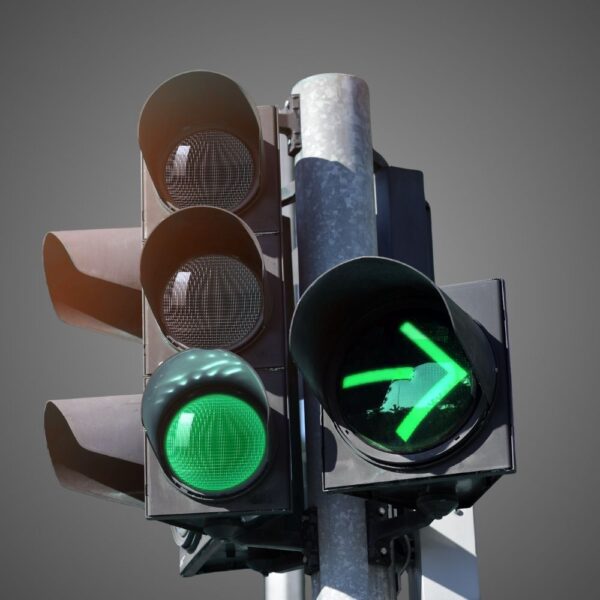



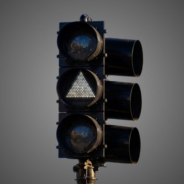




A right-turn arrow module is a component. The permission it communicates depends on the complete signal face, the lane it controls and the operating mode. That is why a replacement discussion should begin with a lane and phase sketch rather than a photograph of an illuminated arrow.
The MUTCD distinguishes shared and separate faces, permissive and protected operation, and changes between modes. The four figures below help connect those choices. Read them with Sections 4F.09 through 4F.15; they show typical arrangements, not model-specific wiring instructions or a complete timing design.
First identify the lane and the road users it crosses
Draw the mandatory right-turn lane, any combined right-turn/through lane, the departure lanes and the pedestrian crossing. Add the opposing left-turn and U-turn movements. A right turn may look geometrically simple, but its permitted operation depends on those interactions. Keep the crossing pedestrian’s route visible in the sketch.
Section 4F.09 treats permissive-only, protected-only, protected/permissive and variable modes separately. Protected/permissive operation includes both types during a cycle. Variable operation changes the applicable mode during different periods or as conditions change. A product description saying “arrow” does not identify any of these operating plans.
The distinction also matters when the through movement stops. A shared lane and an exclusive turn lane do not give the designer the same choices. Section 4F.09 contains explicit limits on indications for combined right-turn/through lanes. Establish that geometry before selecting a face from a diagram.
A shared face serves more than the right turn
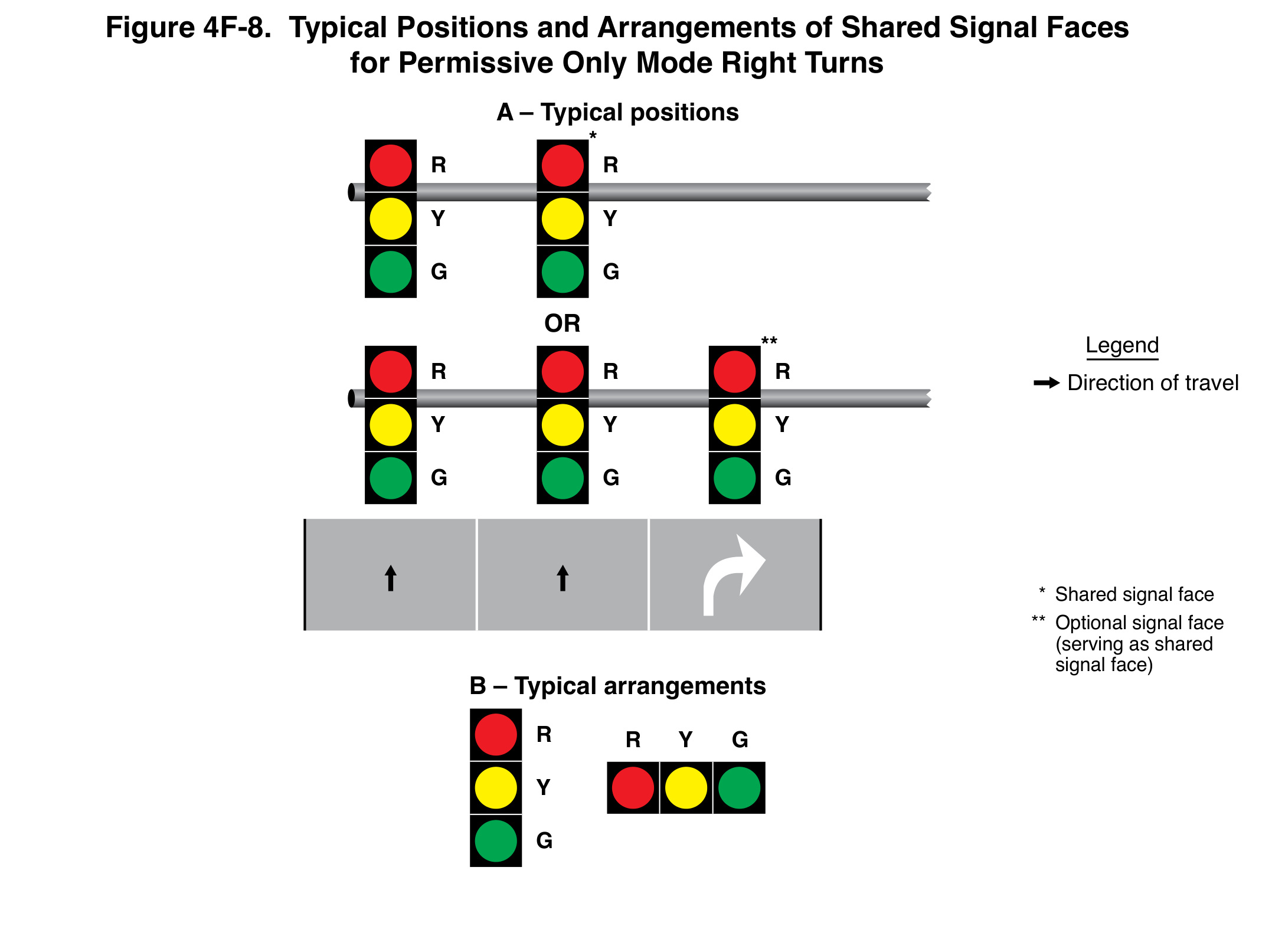
Figure 4F-8 shows shared faces for permissive-only right turns. The shared face controls the turn and the adjacent movement, usually through traffic. Its circular indication follows the same color as the adjacent through faces. During the permissive right-turn movement, the displayed indication is circular green.
That arrangement does not create a dedicated protected right-turn interval. The word “permissive” matters: the movement remains subject to the relevant yielding conditions. The drawing’s lane arrows and the relationship to the neighboring faces help explain why a circular indication cannot be considered independently of the lane and approach.
For an equipment inquiry, identify whether the face being replaced is shared. Counting the number of openings without recording their assigned functions can lead to an apparently compatible part list that no longer matches the intended message. Preserve the complete existing arrangement and the proposed approved change.
A separate flashing-yellow-arrow face has a different boundary
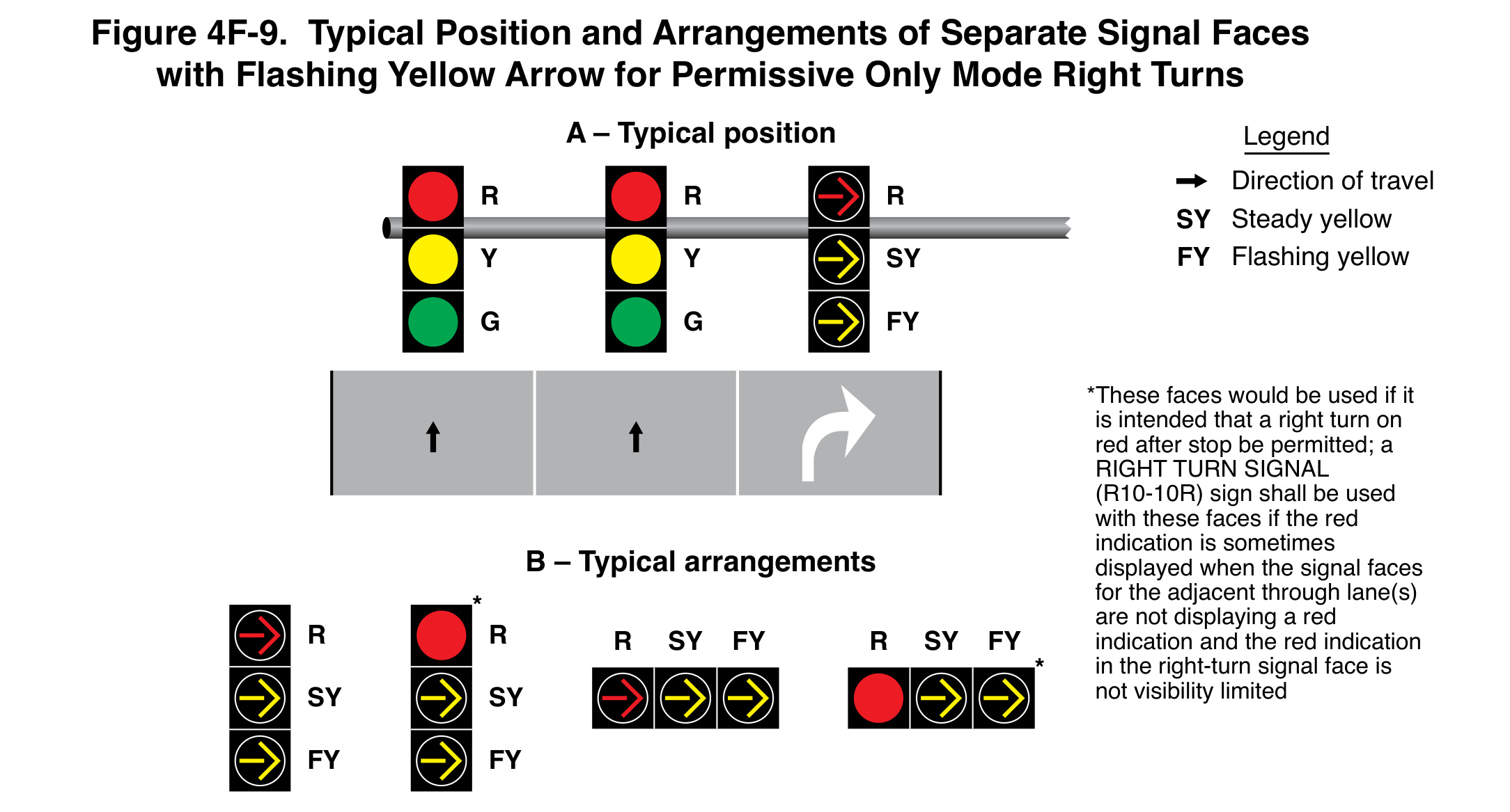
Figure 4F-9 illustrates a separate face with a flashing right-turn yellow arrow for permissive-only operation. Section 4F.11 requires a mandatory right-turn lane for a separate right-turn face and does not permit a circular green indication in that face during this mode. It exclusively controls the right turn and does not serve as a required primary face for through traffic.
The legend distinguishes steady yellow from flashing yellow. They convey different parts of the operation even if a still photograph makes the symbol look identical. A flashing yellow arrow is the permissive display; a steady yellow arrow is used when terminating that movement under the specified sequence. Ask for the operating plan, not just the lamp color.
The figure also retains a note about faces using a circular red indication. Where that red can be displayed while adjacent through faces are not red, the RIGHT TURN SIGNAL sign is required unless visibility limitation makes the right-turn red not readily visible to through drivers. The qualification belongs with the arrangement, not in an optional marketing footnote.
Protected-only operation is not just a brighter arrow
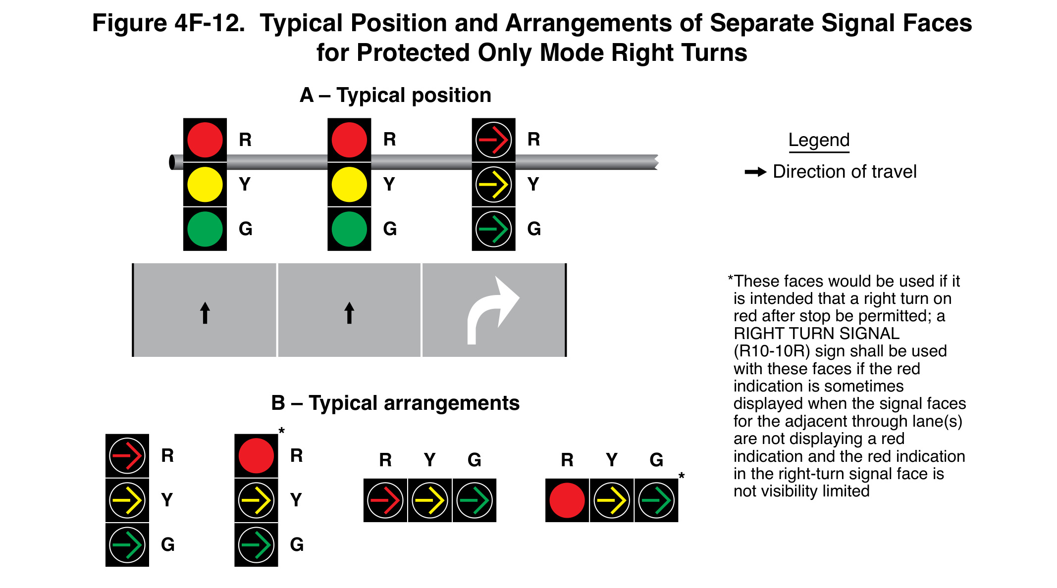
Figure 4F-12 shows separate faces for protected-only right turns. During the protected movement, a right-turn green arrow is displayed. The steady yellow arrow follows the green arrow. Section 4F.13 again ties a separate right-turn face to a mandatory right-turn lane.
Protection is established by the permitted combination of movements and their control, not by the optical output of the green module. Section 4F.09 addresses opposing left turns, conflicting U-turns and pedestrians crossing the departure lanes. Where those pedestrians have signal heads, they display a steady UPRAISED HAND during the protected right turn.
A design review should therefore connect the arrow interval to the conflict and pedestrian-service plan. A green-arrow product can be optically and electrically suitable while an assumed concurrent movement is inconsistent with the intended protected operation. The module submittal and the intersection operating plan answer different questions.
A shared protected/permissive face needs its own comparison
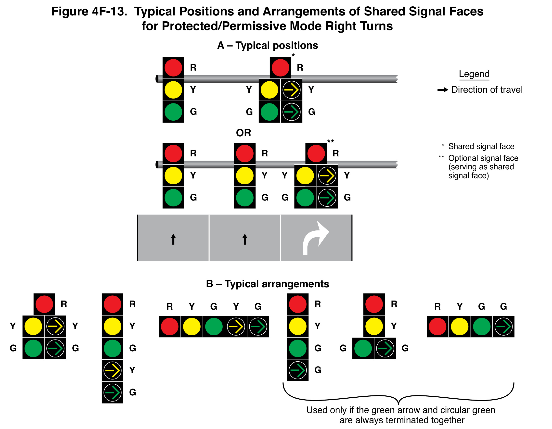
Figure 4F-13 fills a different role from the separate flashing-yellow-arrow arrangement in Figure 4F-14. Under Section 4F.14, the shared protected/permissive face displays circular green during the permissive right turn. Its circular indications follow the color of the adjacent through faces. It should not be described as a separate face that continues a flashing-yellow-arrow right turn while through traffic is stopped.
Retain the bracketed qualification below the arrangements: the indicated faces are used only where the green arrow and circular green always terminate together. The figure also distinguishes a shared face from an optional additional face. These are operating relationships, not interchangeable product photographs. Compare the complete lane assignment, mode and approved sequence before matching individual modules.
Protected/permissive and variable operation need the complete legend
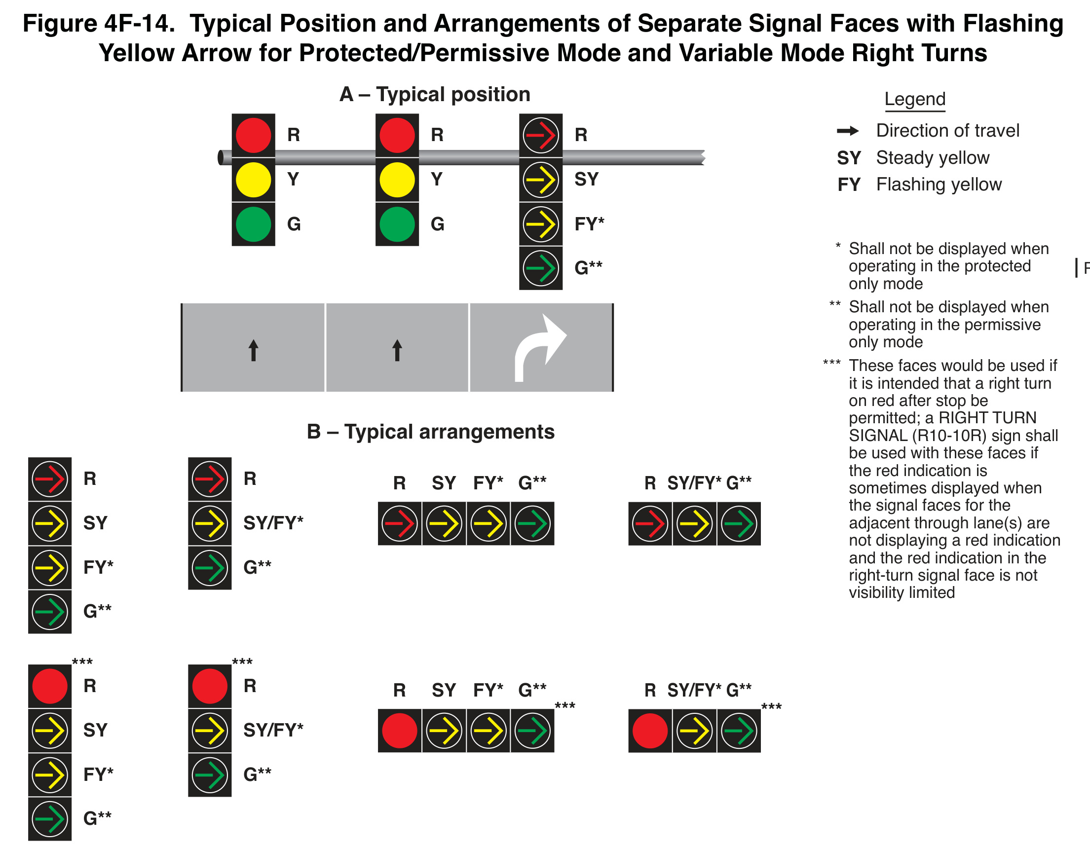
Figure 4F-14 shows separate faces with flashing yellow arrows for protected/permissive and variable modes. The asterisks identify displays that are not used in particular modes. Keeping those notes visible prevents a drawing of available sections from being mistaken for a sequence in which every section is used every time.
Section 4F.15 calls for a green arrow during the protected movement and a flashing yellow arrow during the permissive movement. It permits the permissive flashing yellow arrow while adjacent through traffic is stopped by circular red. That permission relates to the separate turn face and its lane; it should not be transferred casually to a combined through/right lane.
The transition between permissive and protected operation also depends on the opposing movement. Section 4F.15 distinguishes a case in which an opposing permissive left turn is being terminated from one in which it is absent. A single generic animation can omit that distinction. The actual approved sequence should show the relevant condition.
Three sections, four sections and “bimodal” need careful reading
The manual describes separate physical sections for steady and flashing yellow indications in a four-section face, and an applicable three-section arrangement using a bimodal section for those functions. It also describes an option combining green-arrow and flashing-yellow-arrow functions in a bimodal section. “Bimodal” without the specified functions is an incomplete procurement description.
Record which indications the offered unit provides and how they are controlled. Confirm electrical input, wiring interface, monitoring compatibility, mechanical fit and the actual configuration supported by the supplier’s documentation. Do not infer every illustrated behavior from the fact that an item fits a circular opening.
Normal stop-and-go operation and flashing-mode operation also have different provisions about which section supplies the flashing yellow indication. Keep the normal sequence, flash plan and transition review in the same commissioning package. An operational test that covers only one green-to-yellow change does not demonstrate the other states.
Red arrows and circular red are not interchangeable labels
The arrangement and intended right-turn-on-red policy affect which red indication is used. Sections 4F.11, 4F.13 and 4F.15 explain red-arrow and circular-red choices, including the stated exception for a device permitting a turn on steady red arrow. Use the responsible agency’s approved design and applicable traffic rules when interpreting the installation.
For the submittal, record the intended stop-and-remain-stopped message and whether right turns on red are intended to be permitted. Include required signs and any visibility limitation. A photograph of a red lens cannot establish that policy, and replacing the symbol without reviewing it can change the message to drivers.
A practical review sequence for a retrofit
Begin with the lane use and movement inventory. Next identify the face type and operating modes. Then compare the proposed arrangement with the relevant figure and its complete provisions. Finally match the actual module configuration to the accepted arrangement and control requirements. This order keeps a stocked spare from unintentionally becoming the design decision.
For example, a hypothetical approach has one through lane and one mandatory right-turn lane. The agency wants the through movement to stop while permissive right turns continue under a flashing yellow arrow. That request raises a separate-face and conflict-review question; it is not resolved by installing a yellow arrow beside an existing circular red.
The design team still needs to review pedestrian conflicts, opposing movements, signs, visibility, detection, controller configuration and the transition into and out of the requested mode. The example identifies the review tasks rather than approving a configuration. A change that appears to involve one module can cross several system boundaries.
Ask for evidence that follows those boundaries
The equipment record should identify manufacturer, model, symbol direction, color, size, electrical version and supported functions. Connect those details to the appropriate approval-list entry where the project requires one. Keep model suffixes that change input or function visible in the purchase line and accepted submittal.
The commissioning record should identify the tested operating modes, relevant controller states, field observations and unresolved items. Retain evidence for the steady and flashing functions and the intended face visibility. A supplier demonstration of a module on a bench is useful product information, but it does not verify the intersection’s complete operation.
For maintenance, preserve the accepted arrangement and configuration with the asset record. A later technician should be able to distinguish an equivalent replacement from a product still requiring compatibility review. That record is especially valuable where a cabinet has been modified and the original face photograph no longer describes the current installation.
Check the boundary between scheduled modes
A variable-mode installation can look correct during the one period when a reviewer visits it. A practical acceptance plan should identify the scheduled or condition-based changes and verify the intended displays on both sides of each change. Record which mode is active instead of labeling every observation simply “normal operation.”
For a hypothetical schedule that uses protected operation during one period and permissive operation during another, the question includes which indications are suppressed in each mode, how the transition is managed and what the adjacent through and pedestrian faces display. The actual project schedule and approved logic supply the test conditions; the example does not prescribe them. Keep the result connected to that operating plan so maintenance can distinguish a fault from an intentional mode change.
Frequently asked questions
Can a separate right-turn face serve a combined through/right lane?
Sections 4F.11, 4F.13 and 4F.15 require a mandatory right-turn lane for a separate right-turn face. Review combined-lane provisions under Section 4F.09 rather than borrowing a separate-lane diagram.
Does a flashing yellow arrow give the same permission as a green arrow?
No. In these applications, flashing yellow serves permissive operation and green arrow serves protected operation. The relevant conflicts, indications and transitions must agree with the selected mode.
Does a standard yellow-arrow module establish bimodal capability?
No. Identify the exact steady, flashing and color functions required and verify the proposed unit’s documentation and control interface. The term describes a particular function, not a capability implied by every yellow-arrow listing.
Can the MUTCD figure replace a wiring or timing drawing?
No. It explains typical positions and arrangements with conditions. The project needs its approved design, equipment instructions and applicable compatibility evidence for installation and operation.
Sources and product context
- FHWA, MUTCD 11th Edition with Revision 1, Sections 4F.09-4F.15, printed pp. 693-703. Figures 4F-8, 4F-9, 4F-12, 4F-13 and 4F-14.
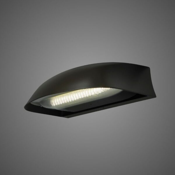
- LEOTEK IL6-P3 arrow module and DT arrow module: review model-specific documents; the figures do not establish suitability for every illustrated mode.
- Signal viewing angle and face placement.
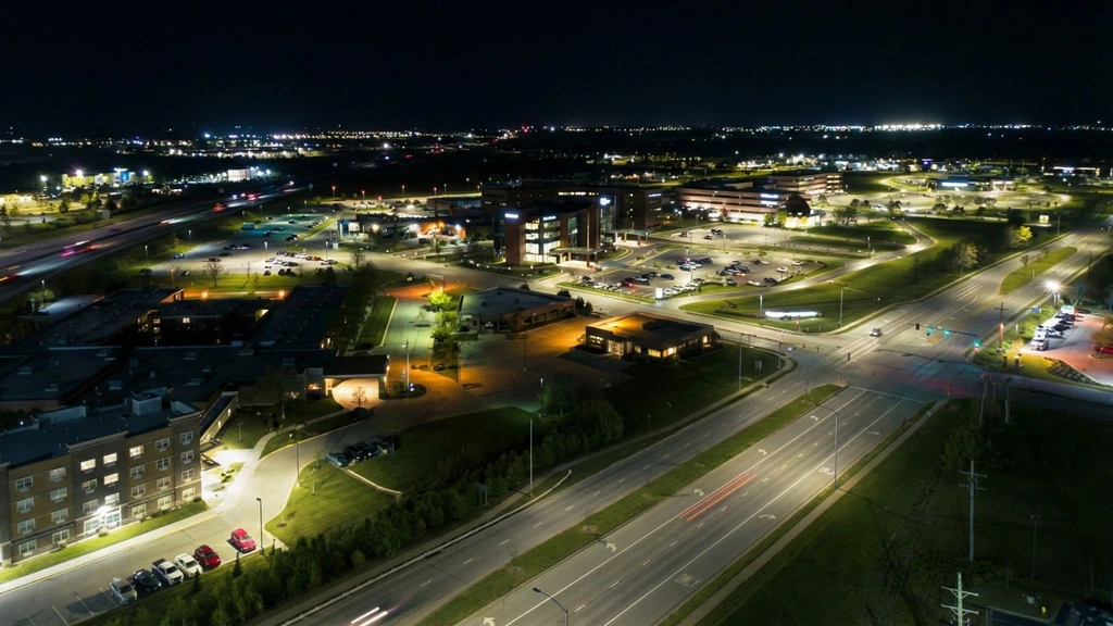
Cover: AI-generated editorial illustration for LEOTEK, not a verified installation, product photograph or test record. Technical figures and the calculation table have separate FHWA source credits.