BABA and Buy American Act (BAA) compliant configurations are available for select LEOTEK roadway and traffic lighting products.
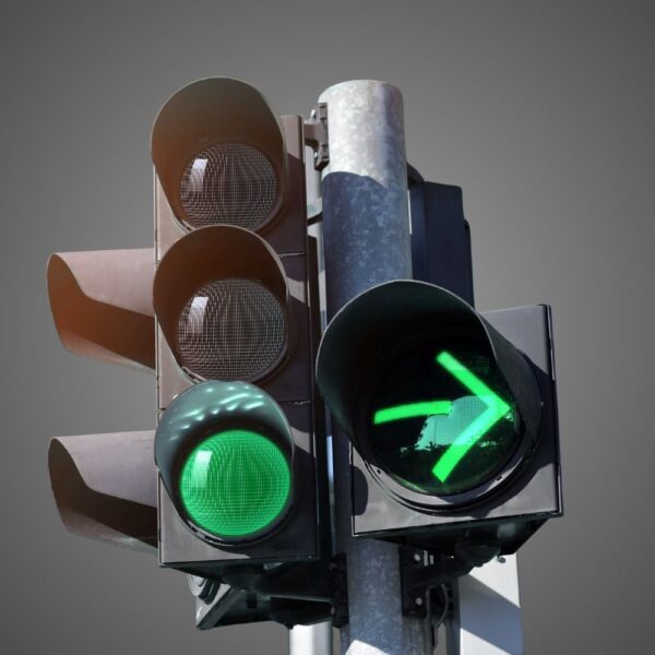
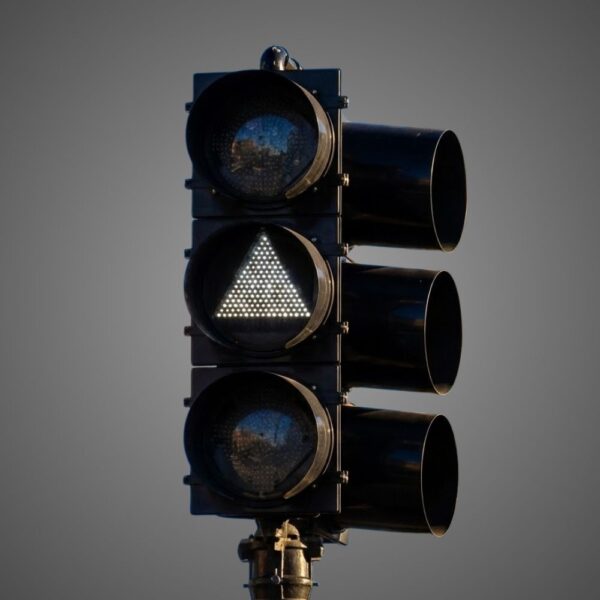
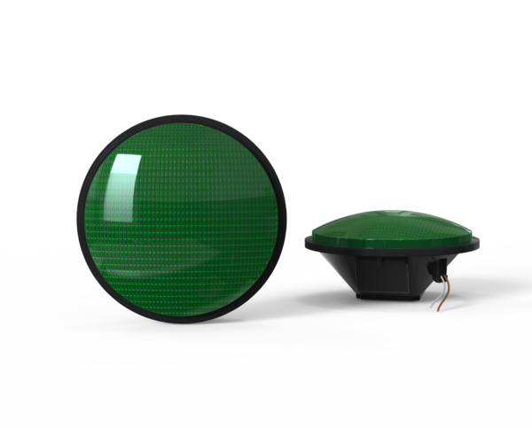
Countdown Signal Module
Hand & Person Overlap
Hand & Person Side by Side
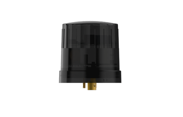
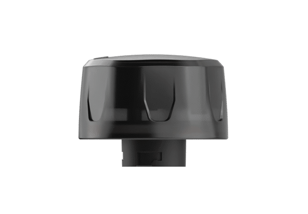
External / Plug-and-Play Smart Node (Mounts externally to the fixture)
Integrable lighting products
Internal / Integrated Smart Node (Built directly inside the luminaire)
Integrable lighting products
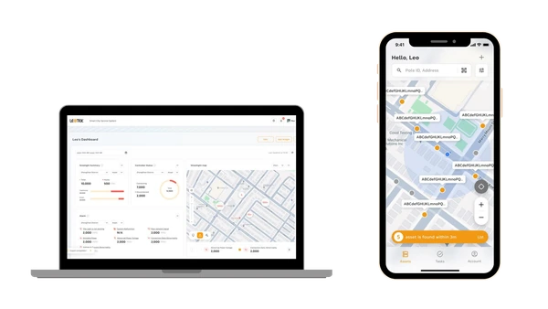
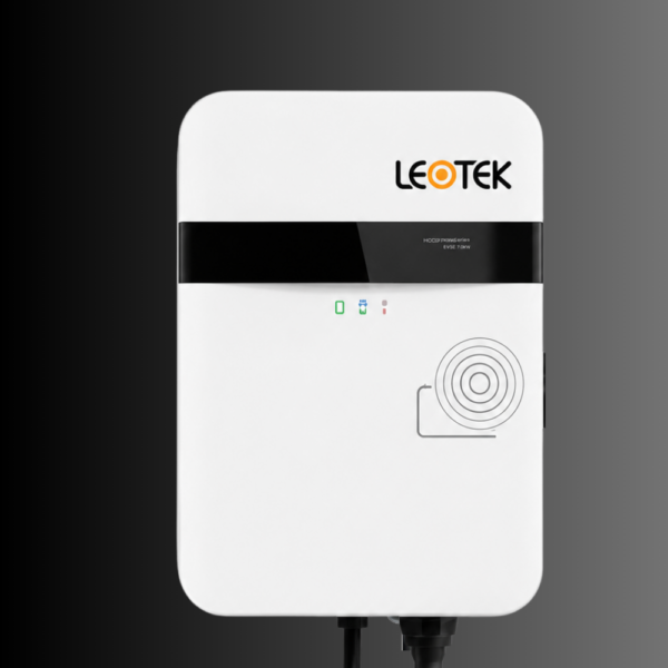
The central AI management system (CMS) of the LEOlink Intelligent Lighting System.
Integrable lighting products
Frontier isn’t just a name—it’s a declaration. Born from the legacy of Dialight’s trusted traffic signal designs and reimagined by LEOTEK’s innovation-driven R&D and product management teams, Frontier stands as a symbol of reliability, evolution, and regional adaptation.
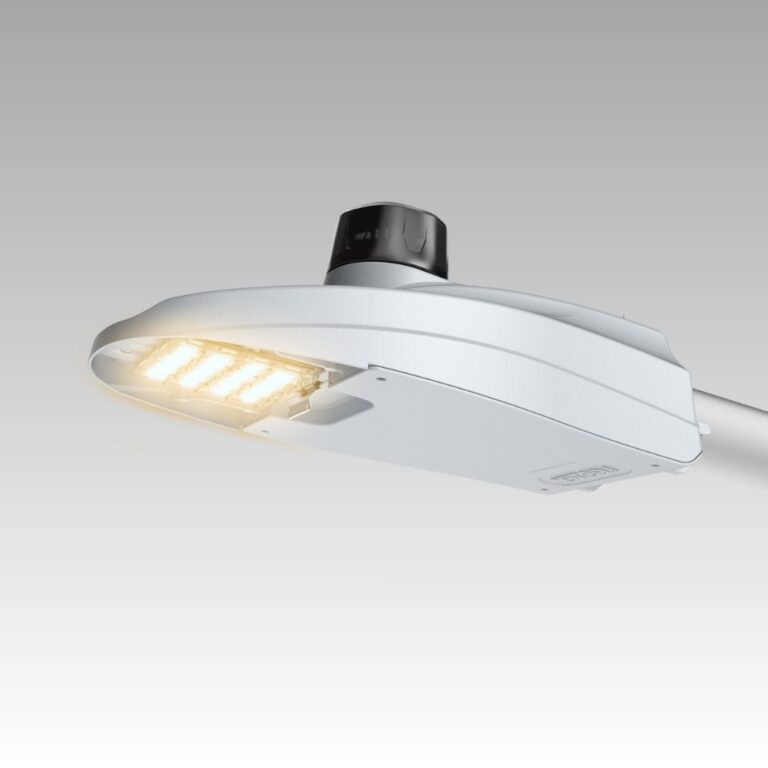
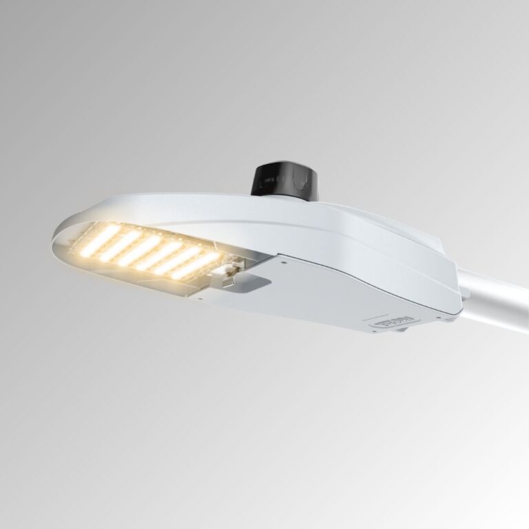
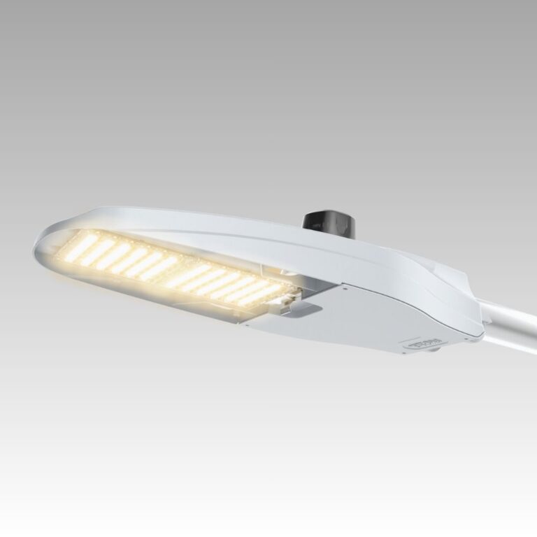
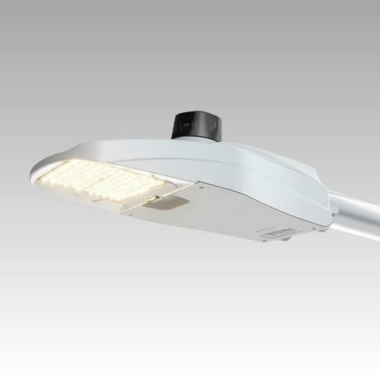
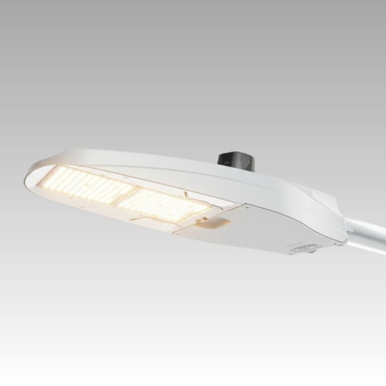
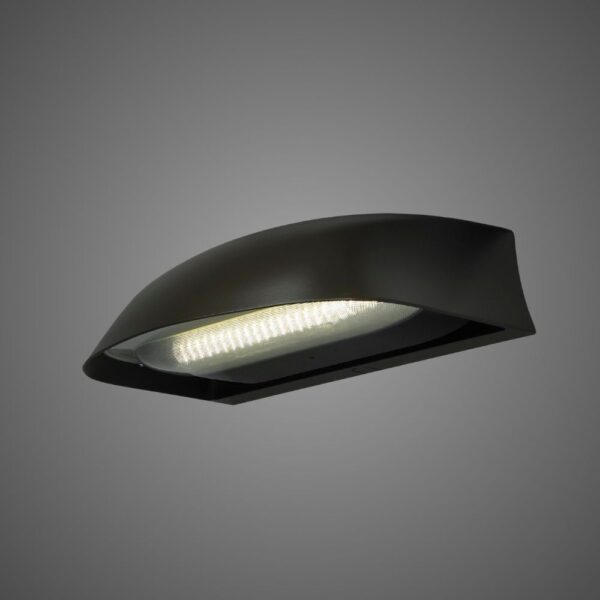
Compare KarbonCobra KC0, KC1, KC2 and ComfortEnhanced LED street lights. Explore model specifications and control options for your roadway project.
Explore related applications: Outdoor lighting applications · All Outdoor Lighting products
Check our LEOLab pages to find more information.
If you need any service, please feel free to contact us!
PROJECT SUPPORT
Answers to common questions about product selection, installation and procurement.
KC0, KC1 and KC2 cover progressively higher output requirements. Published 70 CRI Type 2R table ranges are 1,232–7,964 lm for KC0, 2,158–15,735 lm for KC1 and 10,733–28,939 lm for KC2. KC1CE/KC2CE use a distinct ComfortEnhanced engine and Type II/III optics. These nominal family ranges span configurations; select the exact performance code and IES file for the roadway instead of treating the range as one fixture’s output.
Specifications & documents
karboncobra kc0 · karboncobra KC1 · karboncobra kc2 · KC1CE-Spec-Sheet
Further reading
How to Read an IES File
KC1’s two-bolt slipfitter fits 1¼–2-inch nominal mast arms, corresponding to 1⅝–2⅜-inch outside diameter, with ±5° leveling in 2.5° steps. That supports a practical retrofit assessment. Pole spacing is a separate photometric decision: compare the specified optic, performance code and mounting height against roadway minimum levels and uniformity. Record arm diameter, insertion length, pole condition and circuit voltage before finalizing the fixture schedule.
Specifications & documents
KC1-Spec-Sheet
Further reading
HPS-to-LED Streetlight Conversion: Selection and Retrofit Guide · Roadway Lighting Uniformity Ratios
KC1 offers house-side, front-side, cul-de-sac and 80-degree cutoff shields for different directions of spill or high-angle light. The current sheet excludes its house-side, front-side and cul-de-sac shields from the T5 optical configuration. Choose the shield with the distribution, then calculate the affected roadway and property boundary. A shield added after photometric approval can also remove useful light and should be included in the submitted design.
Specifications & documents
KC1-Spec-Sheet
Further reading
How to Read an IES File
No. KC1CE uses a low-glare engine and angled transition plate, with Type II/III optics; it is a different optical choice from standard KC1’s wider distribution set. CCT is another selection variable. Compare the CE IES file at the actual road geometry and driver viewing positions, and review nearby homes. Neither a CCT label nor a CE suffix alone guarantees zero glare for every mounting height or aiming condition.
Specifications & documents
KC1CE-Spec-Sheet · KC1-Spec-Sheet
Further reading
HPS-to-LED Streetlight Conversion: Selection and Retrofit Guide
The current KC1 sheet assigns IP66 to the optical system and power supply. Complete-luminaire IP54 requires the IP54 option, which includes the rubber wildlife guard. The qualified ambient rating reaches 50°C for supported configurations, but designated performance codes are limited to 40°C. For hot sites, use the specific performance-table footnote rather than applying the maximum temperature headline to every code.
Specifications & documents
KC1-Spec-Sheet
Further reading
How Ambient Temperature Affects LED Streetlights
KC1 lists a 10-year limited warranty for standard luminaires/components and 5 years for motion-sensor configurations. LEOLink controller coverage is selected separately: the ordering table identifies NB01P05, NB01P10 and factory-installed EB01P10. The current North America warranty governs covered defects and remedy conditions. A warranty term is not a forecast of zero maintenance or a blanket promise to cover installation, lifts and every field expense.
Specifications & documents
KC1-Spec-Sheet · Leotek General Illumination Products Warranty North America
The current KC1 sheet requires the explicit BABA ordering option when that build is needed; standard ordering does not establish the BABA build. Include the exact catalog and project documentation in the bid. For lifecycle cost, calculate each configuration’s kWh from its operating watts and dimming schedule, then add controllers, subscriptions, planned maintenance and installation. Keep rebate eligibility and procurement acceptance tied to the exact proposed configuration.
Specifications & documents
KC1-Spec-Sheet
Further reading
BABA vs. Buy American: What Public Lighting Buyers Need to Distinguish
NB01-Plus is the external ANSI seven-pin route with the standard 0–10V driver. EB01 is factory-installed and requires DALI D4i; it is not a plug-in retrofit node. On KC1, D4i and TLR4U/TLR4L options are limited to MV 120–277V. The PS field selector is not compatible with D4i. Select driver, receptacle, node and service plan together instead of combining individually available options.
| Architecture | Required configuration |
|---|---|
| External NB01-Plus | Standard 0–10V driver and compatible ANSI seven-pin interface. Specify the node, supply voltage and RenAI/data-plan terms together. |
| Embedded EB01 | Factory-installed DALI D4i configuration. KC1 D4i is limited to MV 120–277V; PS is not compatible with D4i. |
| PS field selector | Local adjustment with the supported standard driver configuration. This is an output selector, not a CMS or cellular service. |
For example, a KC1 project requiring embedded EB01 should not also request the PS selector or HV D4i. Resolve the driver and voltage architecture before adding controller and service options.
Specifications & documents
KC1-Spec-Sheet · LeoLink Data Sheet 09.15.2025
Further reading
Streetlight CMS Architecture: Nodes, Networks and Central Management
Provide road width/classification, pole coordinates, mounting height, arm length, setback, existing circuits and target lighting criteria. Identify the proposed KC model, performance code, CCT, CRI, optic and shield so the calculation uses the corresponding IES file. Also distinguish MV/HV, standard versus D4i controls and the required BABA build. The resulting fixture schedule should reproduce the configuration used in the approved calculation.
Specifications & documents
KC1-Spec-Sheet · karboncobra kc2
Further reading
How to Read an IES File
Choose a roadway luminaire around the lighting task, pole layout and long-term operating plan. The KarbonCobra family provides model choices for different roadway applications, with project selection based on documented photometric performance and the exact fixture configuration.
Start with KC0 for smaller-scale residential and pedestrian-oriented applications, KC1 for local and city streets, and KC2 for larger roadway applications. Compare KC1CE and KC2CE ComfortEnhanced alternatives when visual comfort is a project priority. These are starting points for evaluation; final selection depends on the model’s output, distribution and performance in the actual layout.
Provide mounting height, pole spacing, road width, arm length, setback, tilt and the agency’s lighting criteria. Evaluate the exact configuration’s IES file for average and minimum light levels, uniformity and relevant glare or spill-light requirements. A higher wattage or lumen package does not by itself establish better roadway performance.
Confirm the existing arm dimensions, attachment method, luminaire loading, supply voltage, wiring and grounding. Define photocontrol, dimming and network-control requirements when selecting the fixture. Review connector and driver compatibility for the proposed controller. If future smart controls are planned, include that requirement in the initial fixture schedule.
Include fixtures, installation, energy, scheduled maintenance, drivers and other service items, access equipment, traffic control and controls-related costs. Use a common analysis period and tariff assumptions, including fixed or unmetered charges where relevant. Separate documented product performance from assumptions about replacement intervals, and compare more than one maintenance scenario.
Request the current model specification, exact configuration IES file, installation instructions, applicable listing and procurement documentation, and the current North American general illumination warranty. Identify shielding, finish, CCT, voltage and control requirements by ordering code. For coastal sites, review finish selection and the written warranty conditions before the order is finalized.