


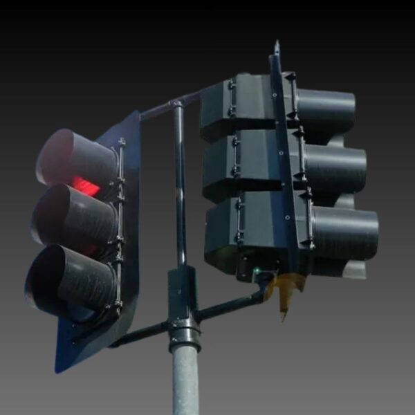


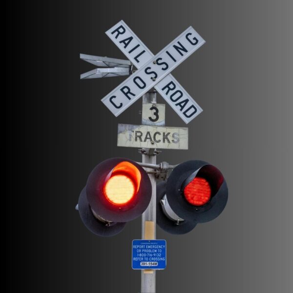
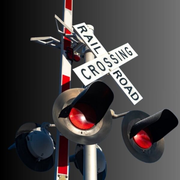





A grade-crossing signal drawing can prevent a basic purchasing mistake: confusing the optical module with the complete warning installation. The red indication, housing, background, support, gate, detection and power system occupy different parts of the design. A correct replacement module does not by itself establish correct clearances or coordinated operation.
Two MUTCD figures are particularly useful when reviewing that boundary. Figure 8D-1 combines the principal warning hardware and clearance references; Figure 8D-2 shows how entrance and exit gate layouts change with crossing angle. Read both with Chapter 8D, not as construction details for an unreviewed site.
Read the composite as several systems sharing a location
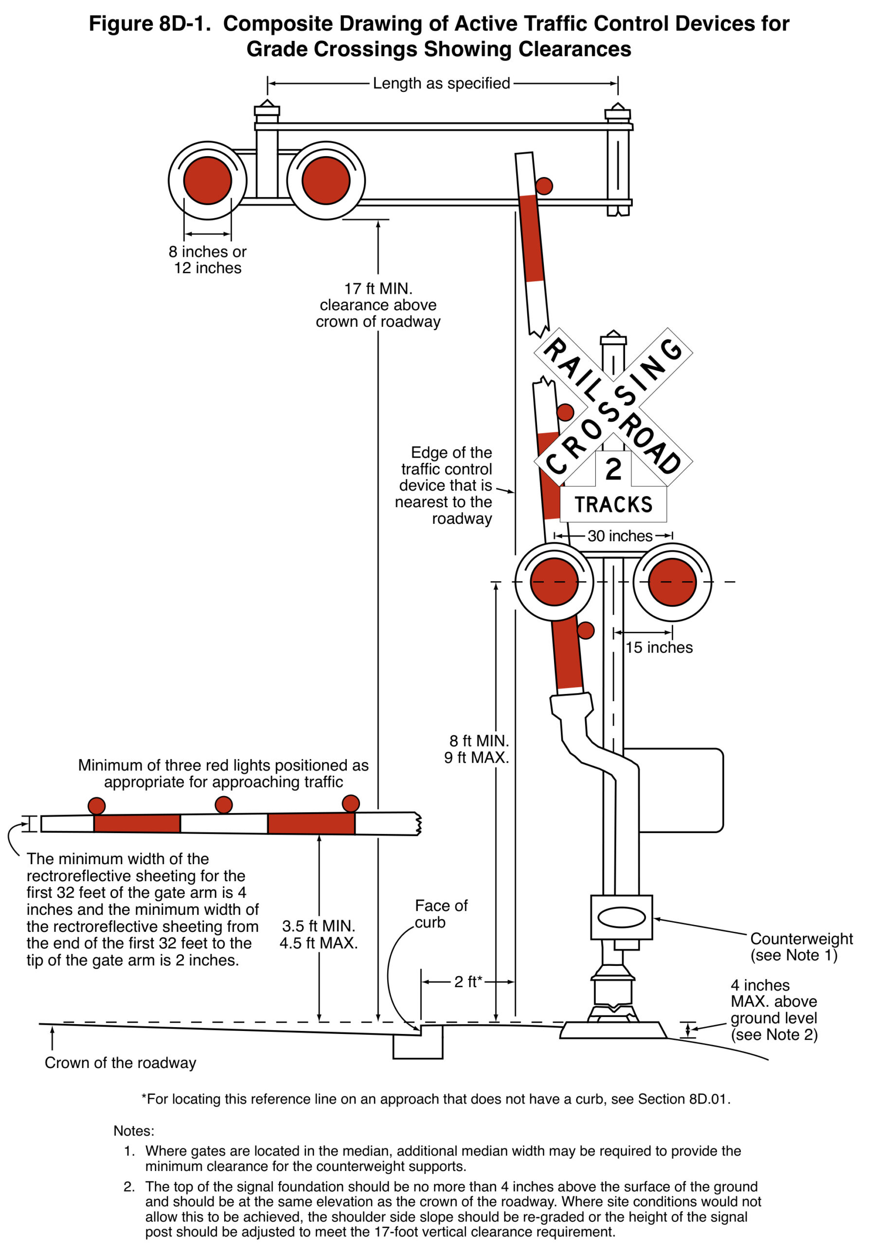
Figure 8D-1 includes a post-mounted pair of flashing red lights, an overhead arrangement and an automatic gate assembly. It puts the visible equipment in relation to the roadway, curb, gate position and mounting references. Those relationships explain why the dimensions of an LED insert cannot describe the envelope of the complete installation.
The manual identifies nominal 8-inch or 12-inch lenses for grade-crossing flashing-light units. It also makes clear that references to lenses do not restrict the optical technology to incandescent assemblies. A nominal diameter therefore describes one aspect of the optical unit; it does not establish the depth, sealing interface, connections or acceptance of a proposed replacement.
For an inquiry, photograph and identify the existing complete assembly and obtain the relevant drawings. Keep the housing, module and mounting interfaces separate in the comparison. Do not scale a component from the MUTCD illustration or from the apparent size of a head in a roadside photograph.
Clearances have different reference points
Section 8D.01 specifies at least a 2-foot horizontal offset from the face of a vertical curb to the nearest part of the signal or upright gate arm where a curb is present. Without a curb, the shoulder and traveled-way provisions describe different reference conditions. Identify which condition applies before measuring or interpreting a site sketch.
For a cantilevered-arm flashing-light signal, the stated minimum vertical clearance is 17 feet above the roadway crown to the lowest point of the unit. The ordinary post-mounted flashing-light height guidance uses the center of its housing and a different 8-to-9-foot range. These are not alternative heights for the same reference point.
The figure’s foundation note also retains a site-condition qualification. Clearances to the closest track require the applicable railroad or transit-agency and regulatory standards. A highway-side dimension on this composite does not settle the railway clearance envelope or the support design.
Keep a pedestrian route in the site review
Chapter 8D advises maintaining sufficient clearance for pedestrian travel where a pedestrian route is provided. A support that clears vehicle traffic can still obstruct the walking path or place a gate mechanism near the route. Include sidewalks, pathways, counterweights and the gate’s positions on the actual plan.
The lowered gate-arm height guidance is measured above the roadway crown, while the counterweight must remain outside the traveled way, sidewalk or pathway in that position. Review the full moving assembly rather than checking only the gate tip or the post. The component manufacturer’s mechanical drawing is important for that review.
A site photograph is useful context, but it cannot show the complete range of movement, buried constraints or every road-user approach. Carry the measured geometry into the Diagnostic Team’s review and the accepted design. The illustration helps formulate the question; it is not a substitute for those measurements.
Flashing-light operation is a system function
Section 8D.02 describes two horizontally arranged red lights flashing alternately toward approaching highway traffic. Each lamp’s flash rate is specified separately, from 35 to 65 flashes per minute, with approximately equal illumination periods. Counting the alternations of the pair as if they were one lamp can produce a misleading check.
The chapter also addresses which approaches and lanes the warning serves, back-to-back arrangements and supplemental overhead or additional units. A replacement part may match the electrical input while the complete installation still needs review for an obscured or newly added approach. The visibility question belongs to the road-user view, not just the module’s illuminated face.
Procurement should identify what the supplier is furnishing: an optical module, complete light unit, signal assembly or a broader system. Ask separately for the documentation supporting the offered configuration, the mechanical interface and the applicable project acceptance. A generic “railroad signal” description leaves those boundaries unresolved.
Four-quadrant describes closure, not a gate count
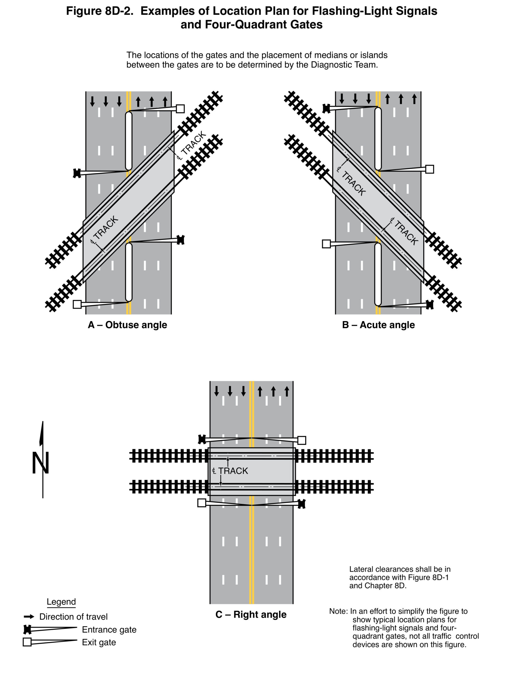
Figure 8D-2 includes obtuse-angle, acute-angle and right-angle examples. The crossing angle changes the relationship between tracks, roadway lanes, entrance gates, exit gates and any median. The note states that the Diagnostic Team determines gate locations and the placement of medians or islands between them.
Section 8D.05 defines a Four-Quadrant Gate system by control of all entrances and exits to provide full closure. It does not mean that every installation has exactly four physical gates. An Exit Gate system can include gates on some, but not all, exiting lanes and therefore not be a Four-Quadrant Gate system.
The drawing is also deliberately simplified: it omits flashing-light signals and other traffic-control devices. Their absence from the plan is not permission to omit them from a complete design. Keep that note with the figure when using it in an article, a product discussion or a review meeting.
Entrance and exit gate behavior should not be merged
The manual requires the entrance gate mechanism to fail safe in the down position. It generally requires the exit gate mechanism to fail safe in the up position, with a stated exception tied to remote health monitoring. Treating every gate as having the same failure position overlooks the different roles of preventing entry and allowing escape.
Exit gate operating mode and clearance time involve the Diagnostic Team and, depending on the mode, timing or vehicle detection. The design vehicle’s length and the time needed to clear the minimum track clearance distance matter. Installing a different lamp does not establish those functions or verify that a vehicle can leave the crossing.
For acceptance, keep the gate, detection and warning-system checks separate from the optical-module inspection. They should be coordinated within the project, but a passed item in one category is not evidence that the others have been tested. Record which organization owns each verification and any unresolved condition.
A nearby highway signal creates an interface to review
Section 8D.09 describes the interconnected grade-crossing warning system and highway signal as a combined system. The preemption sequence depends on information from both sides. The review therefore needs the highway agency, railroad or transit agency and other responsible authorities, rather than a cabinet-only check.
The chapter recommends rail preemption for specified signal-controlled locations 200 feet or less from a crossing with flashing-light signals, unless otherwise determined by the Diagnostic Team. It also recommends considering coordination and queue-related measures beyond 200 feet. Distance alone does not remove the possibility of vehicles queuing into the track-clearance area.
A separate requirement applies where highway signal faces are within 50 feet of any rail and crossing flashing-light signals are present. Do not combine that standard with the 200-foot guidance into one simplified rule. The correct question includes both the applicable provision and the way vehicles can occupy the space between controls.
Back-up power has more than one boundary
Section 8D.02 requires grade-crossing flashing-light signals to operate at low voltage using storage batteries as primary or standby energy, with charging provision. Guidance elsewhere addresses back-up power for adjacent highway signals with preemption or coordinated crossing operation. Those statements concern related equipment, but not necessarily the same battery system.
For a module replacement, verify the actual supply, operating conditions, connections and compatibility with the complete warning equipment. For a system power review, include the relevant loads, battery condition, charging, operating duty and inspection responsibilities. A low module wattage alone does not establish a guaranteed outage runtime for the installation.
Keep standby behavior and restoration checks within the responsible agencies’ procedures. The useful purchasing record states what was supplied and what evidence supports it, without implying that a component quotation covers train detection, gates, preemption, batteries and site acceptance.
The gate-arm lamp is a different component
The small red lamps on a gate arm should not be confused with the larger flashing-light units on the post or overhead support. Section 8D.03 describes typical circular gate-arm lamps as approximately 4 inches in diameter, and recognizes rectangular lamps with approximately the same illuminated area. This is separate from the nominal 8-inch or 12-inch optical diameter described for the crossing flashing-light units.
The gate-arm operating pattern also has a separate role: when activated, the lamp nearest the tip is continuously illuminated while the other gate-arm lamps flash in the specified relationship to the main flashing-light signals. The shared red color does not establish interchangeable dimensions, duty or installation requirements.
For a parts request, name the component and its location before quoting a diameter. A field photo should show enough surrounding equipment to identify whether the requested part is in the main warning pair or on the arm. Follow with the actual part drawing and electrical information. This simple distinction prevents a scale comparison from becoming an incorrect order.
Build a handover that maintenance can use
Retain the accepted model and configuration, drawing references, installation location, inspection results and responsibility boundaries. Note any change to a housing, aiming, wiring or other interface that accompanies the replacement. A future crew should be able to identify the installed item without inferring it from a generic family photograph.
For interconnected sites, Chapter 8D describes regular joint inspections as a best practice and identifies preemption operation, warning or preemption time and highway signal timing among the matters checked. Preserve the relevant joint records with the asset information. They explain system behavior that a component label cannot.
The practical value of these two figures is a better review conversation. One makes the physical assembly and reference points visible; the other makes the road-and-track geometry visible. Together they help prevent a narrow replacement request from concealing a broader installation or operating question.
Frequently asked questions
Does a 12-inch module define the complete signal-head size?
No. Nominal optical diameter is only one dimension. Check the housing, module envelope, mounting, background and electrical interfaces using the actual drawings and proposed configuration.
Does four-quadrant always mean four gate arms?
No. The MUTCD definition concerns full closure of entrances and exits. The number and placement of physical gates depend on the accepted site design.
Can Figure 8D-2 be used as a complete construction plan?
No. It is a simplified location example and explicitly omits other traffic-control devices. Use the complete provisions, Diagnostic Team decisions and accepted project documents.
Does an LED-module replacement verify the entire crossing system?
No. Optical, mechanical and electrical compatibility are part of the review. Gates, detection, warning sequence, power and any highway-signal interconnection require their own coordinated verification.
Sources and product context
- FHWA, MUTCD 11th Edition with Revision 1, Chapter 8D: Sections 8D.01-8D.05 and 8D.09; Figures 8D-1 and 8D-2. Complete provisions include conditions and exceptions not represented by a component photograph.
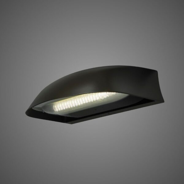
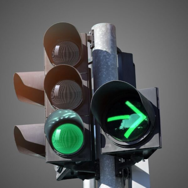
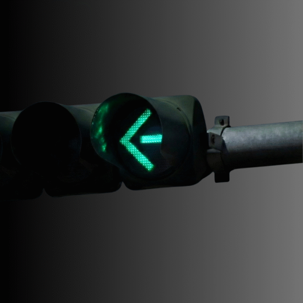
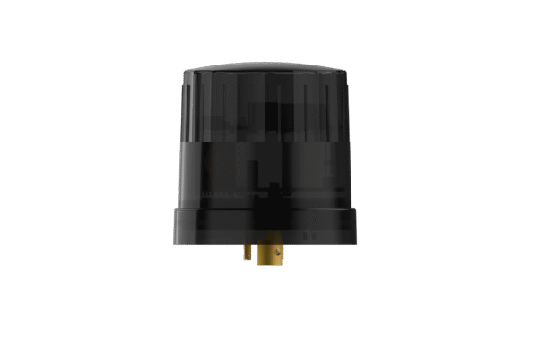
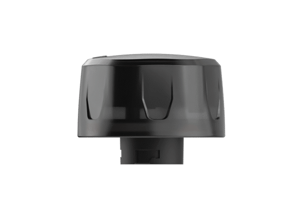
- LEOTEK IL Series grade-crossing module and EV Series grade-crossing module: obtain the exact configuration and current product documentation for the proposed item.
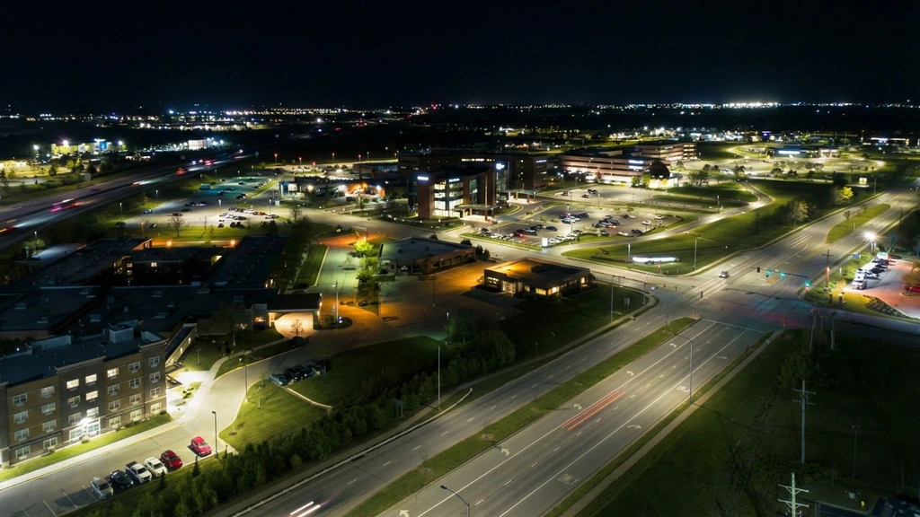
Cover: AI-generated editorial illustration for LEOTEK, not a verified installation, product photograph or test record. Technical figures and the calculation table have separate FHWA source credits.