TOP BAR
DT Series

DT Series Traffic Signal Module – Arrow

Intertek ETL VerifiedRoHS compliantISO 9001 Registered

Availability varies by configuration; see the specification sheet.

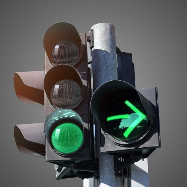
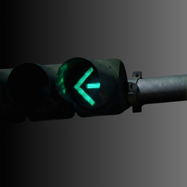
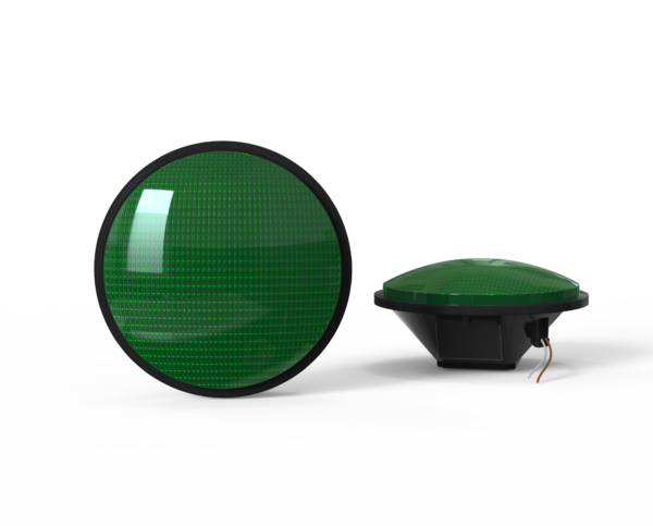
The DT Series extended-life 12-inch LED traffic signal arrow supplies red, yellow and green directional indications for compatible signal heads. Its dedicated thermal and power-supply design targets longer replacement intervals for municipal and DOT signal assets.

The DT arrow specification lists 80–135 Vac operation, 6 W red, 10 W yellow and 6.8 W green model draws, Intertek ETL verification and a 15-year limited full-performance warranty. Match indication color, lens option and housing to the selected order code.

Features

Configuration & Electrical

  • 12-inch red, yellow and green directional arrow modules at 80–135 Vac.
  • Published power: 6 W red, 10 W yellow and 6.8 W green.
  • Tinted lens standard; -CLR indicates the listed clear-lens option.

Optics & Field Performance

  • Intertek ETL-verified DT arrow entries appear in the published specification.
  • Extended-life LEDs, overmolded weatherized connectors and constant-current output.
  • 15-year limited full-performance warranty for the DT arrow family.

Selection & Related Resources

Specifications

Color
Red, Green, Yellow
Indication
Arrow
Lens Color
Clear, Tinted
Lens Size
12"
Voltage
120Vac (80-135Vac)
Certification
ETL

Resources

Application & design reference

Right-turn modes: check the face before selecting a module

The lane, complete face and operating mode determine which message an arrow must communicate. Use the approved design, then verify the exact module and control interfaces.

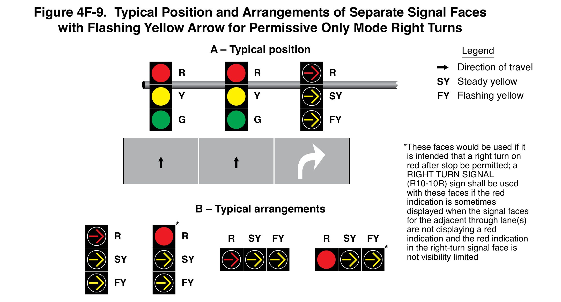
FHWA Figure 4F-9: Typical Position and Arrangements of Separate Signal Faces with Flashing Yellow Arrow for Permissive Only Mode Right Turns.
FHWA, MUTCD 11th Edition with Revision 1 (December 2025), Figure 4F-9, printed p. 695 / PDF p. 736. Original figure and provisions. Select the image to read the full-resolution notes.

A separate permissive right-turn face

Figure 4F-9 shows a flashing-yellow-arrow arrangement for permissive-only right turns. Section 4F.11 requires a mandatory right-turn lane for a separate face and does not permit a circular green indication in that face during the mode.

Keep the steady/flashing legend and red-indication note with the arrangement. Where a circular red can be seen by through drivers while their faces are not red, the stated sign or visibility-limitation provision matters.

The drawing does not establish that every yellow-arrow module supports the illustrated functions. Verify the exact model, input, functions and compatibility for the project.

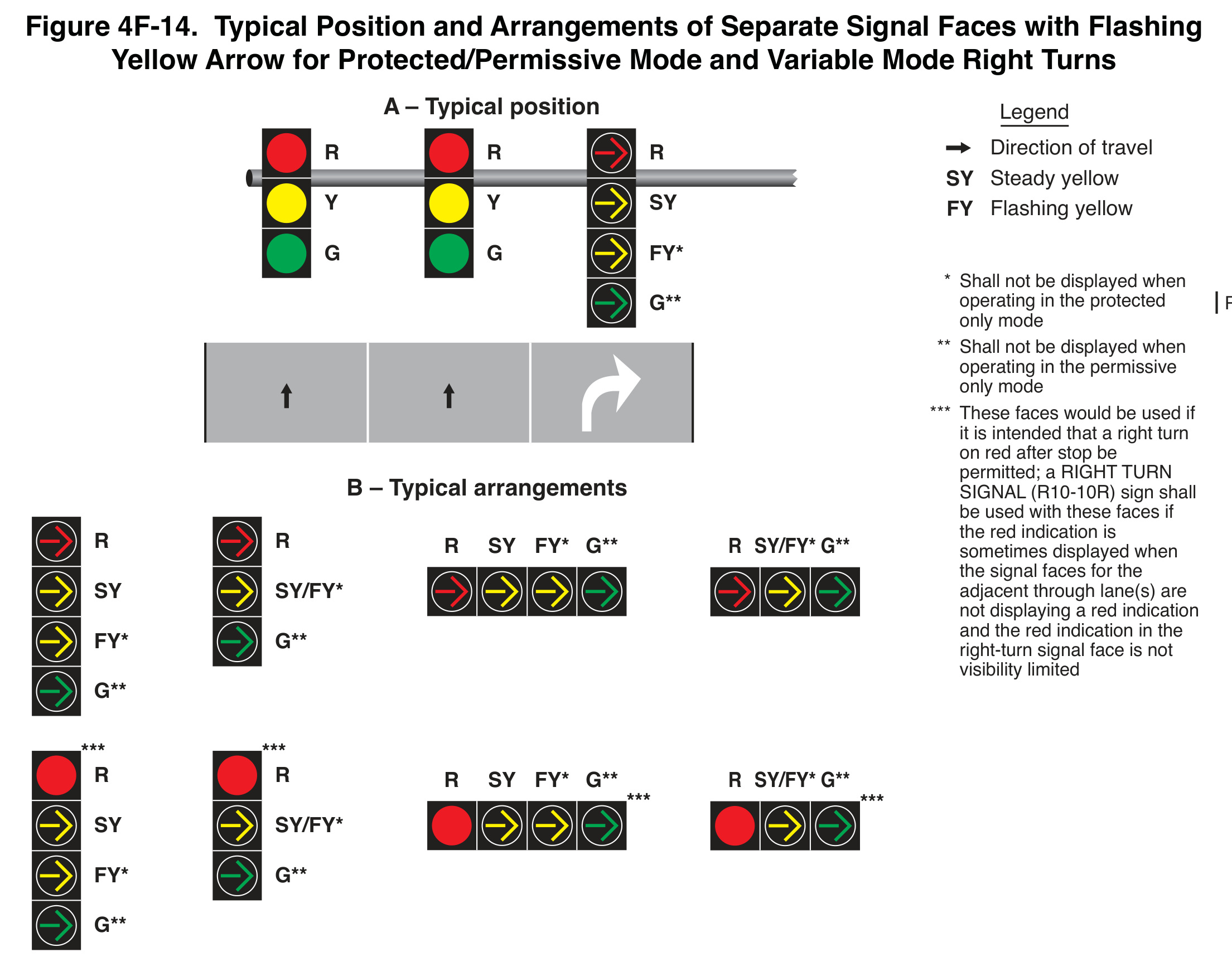
FHWA Figure 4F-14: Typical Position and Arrangements of Separate Signal Faces with Flashing Yellow Arrow for Protected/Permissive Mode and Variable Mode Right Turns.
FHWA, MUTCD 11th Edition with Revision 1 (December 2025), Figure 4F-14, printed p. 701 / PDF p. 742. Original figure and provisions. Select the image to read the full-resolution notes.

Protected/permissive and variable operation

Figure 4F-14 distinguishes protected green-arrow and permissive flashing-yellow-arrow displays. Its asterisks identify indications suppressed in particular modes. Preserve those qualifications when comparing configurations.

A steady photograph cannot verify flashing behavior or the transition between modes. The submittal should identify the complete face, controller configuration, pedestrian and vehicle conflicts, and required compatibility evidence.

Read the complete right-turn guide with four MUTCD arrangements.

Does selecting a yellow-arrow module create a flashing-yellow-arrow installation?

The module is one component. Verify the required functions, complete face, controller, wiring and compatibility. A model listing or a matching opening does not establish the entire operating sequence.

Can the same diagram be applied to a combined through/right lane?

The separate-face provisions require a mandatory right-turn lane. Combined lanes have their own restrictions under Section 4F.09; do not transfer a separate-lane arrangement without the design review.

Does bimodal mean every unit provides the same functions?

No. Identify the particular steady, flashing and color functions required. Obtain documentation for the proposed configuration and its electrical/control interface.

Are these LEOTEK model-specific wiring instructions?

No. They are original MUTCD application figures. Use the approved project design and the exact equipment documentation for installation, operation and acceptance.

Discuss the required configuration with LEOTEK

Related Products

LD Arrow Traffic light module
Indication: Arrow
Voltage: 120Vac (80-135Vac)
IL6-P3 Series Traffic Signal Module – Arrow
Indication: Ball
Voltage: 120Vac (80-135Vac)
IL6-P3 Series Traffic Signal Module – Arrow
Indication: Arrow
Voltage: 120Vac (80-135Vac), 10-28Vdc, 48Vdc (36-60Vdc)
PV Series LED module (3)
Indication: Ball
Voltage: 70-135Vac

LEOTEK's Cases

Looking for More Information?
Connect with LEOTEK

Need a quote or more details about our collaboration? At LEOTEK, we’re ready to provide you with professional advice and friendly service, bringing you closer to a smart and sustainable future.

English
Español
繁體中文