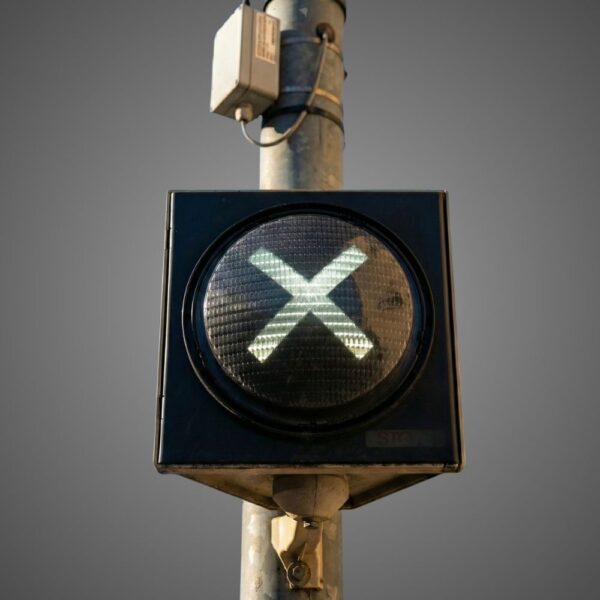
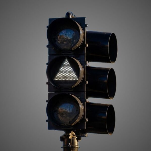
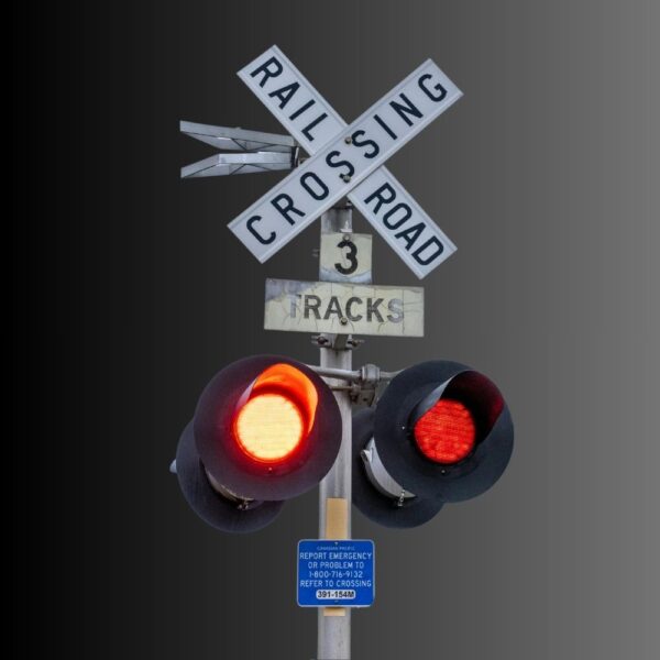
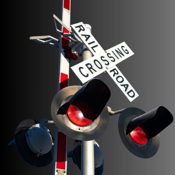
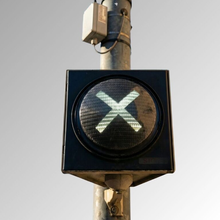
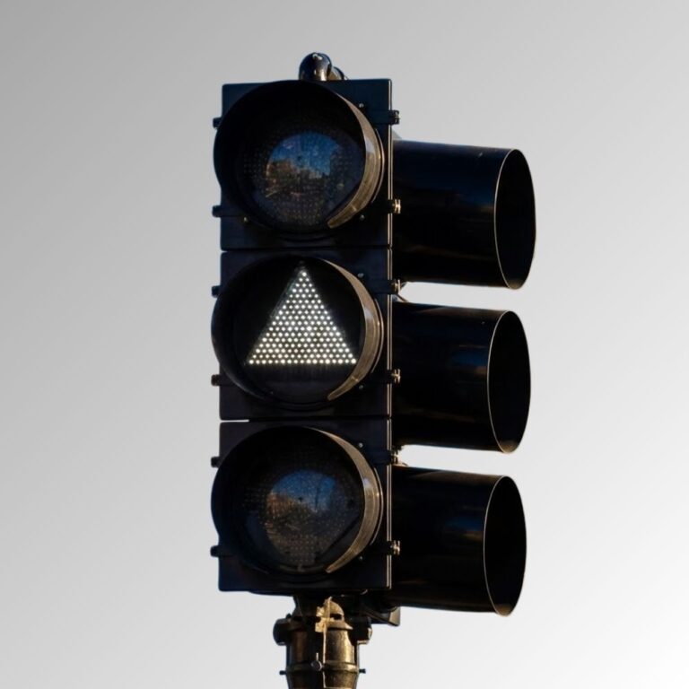
Frontier isn’t just a name—it’s a declaration. Born from the legacy of Dialight’s trusted traffic signal designs and reimagined by LEOTEK’s innovation-driven R&D and product management teams, Frontier stands as a symbol of reliability, evolution, and regional adaptation.
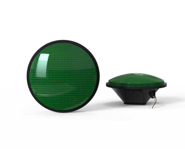
EV Series 12″ Railroad Grade Crossing Signal Module
Availability varies by configuration; see the specification sheet.
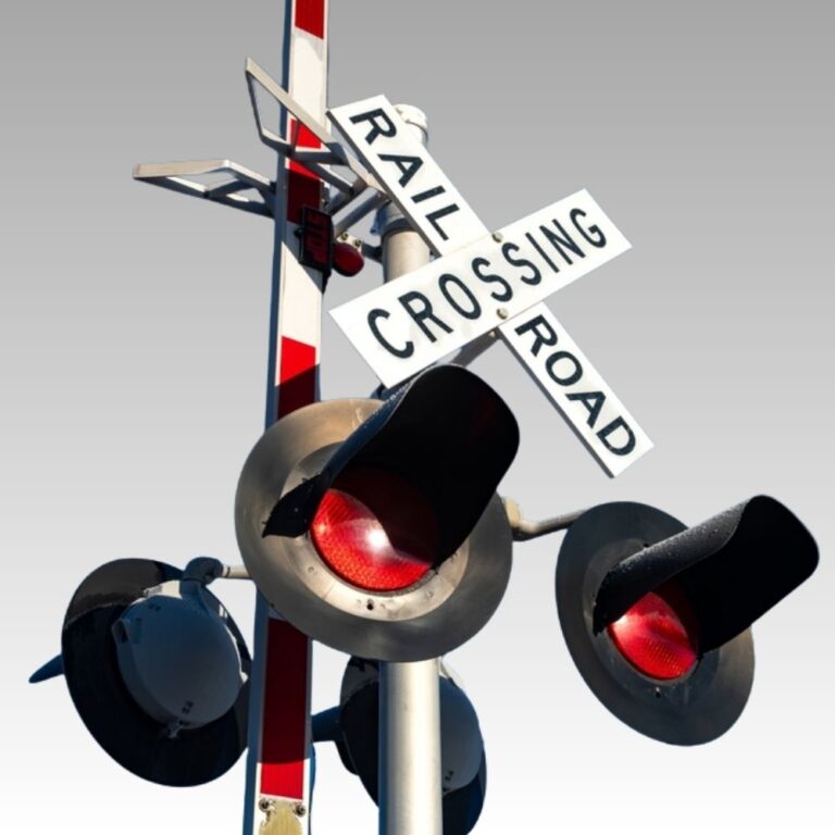
The EV Series 12-inch LED railroad grade crossing signal module provides a red crossing warning indication with low-wattage options and red or white side lights. It is intended for compatible rail-crossing signal heads and controller systems, rather than transit bar or triangle indications.
The EV data sheet lists several supply configurations and model-specific ranges. It shows 8–20 Vdc / 8–16 Vac for the main listed operating range and a separate 8–14 Vdc / 8–16 Vac entry for the unregulated TSL-12RCS-EVW-U1. The Resources folder labels use different nominal ranges, so confirm the exact power-supply model and electrical drawing before ordering.
Features
Configuration & Electrical
12-inch red LED railroad grade-crossing indication with optional red or white side lights.
Published EV order table includes linear, regulated and unregulated model entries with 9.8–10 W listed draw.
Electrical range is model-specific: the spec table shows 8–20 Vdc / 8–16 Vac and a separate 8–14 Vdc / 8–16 Vac U1 entry. Confirm the ordered version.
Visibility & Durability
AREMA and Transport Canada requirements appear in the EV data sheet; confirm bid-specific approval evidence separately.
Hard-coated UV-stabilized polycarbonate lens, moisture-resistant design and optical treatment intended to reduce phantom-signal appearance.
Published 70% intensity at 100,000 operating hours, <75 ms response and five-year limited warranty.
Railroad crossing systems: where the optical module fits
An LED optical module is part of a larger warning installation. Keep the module, housing, supports, gates, detection, power and highway-signal interfaces distinct in the project review.
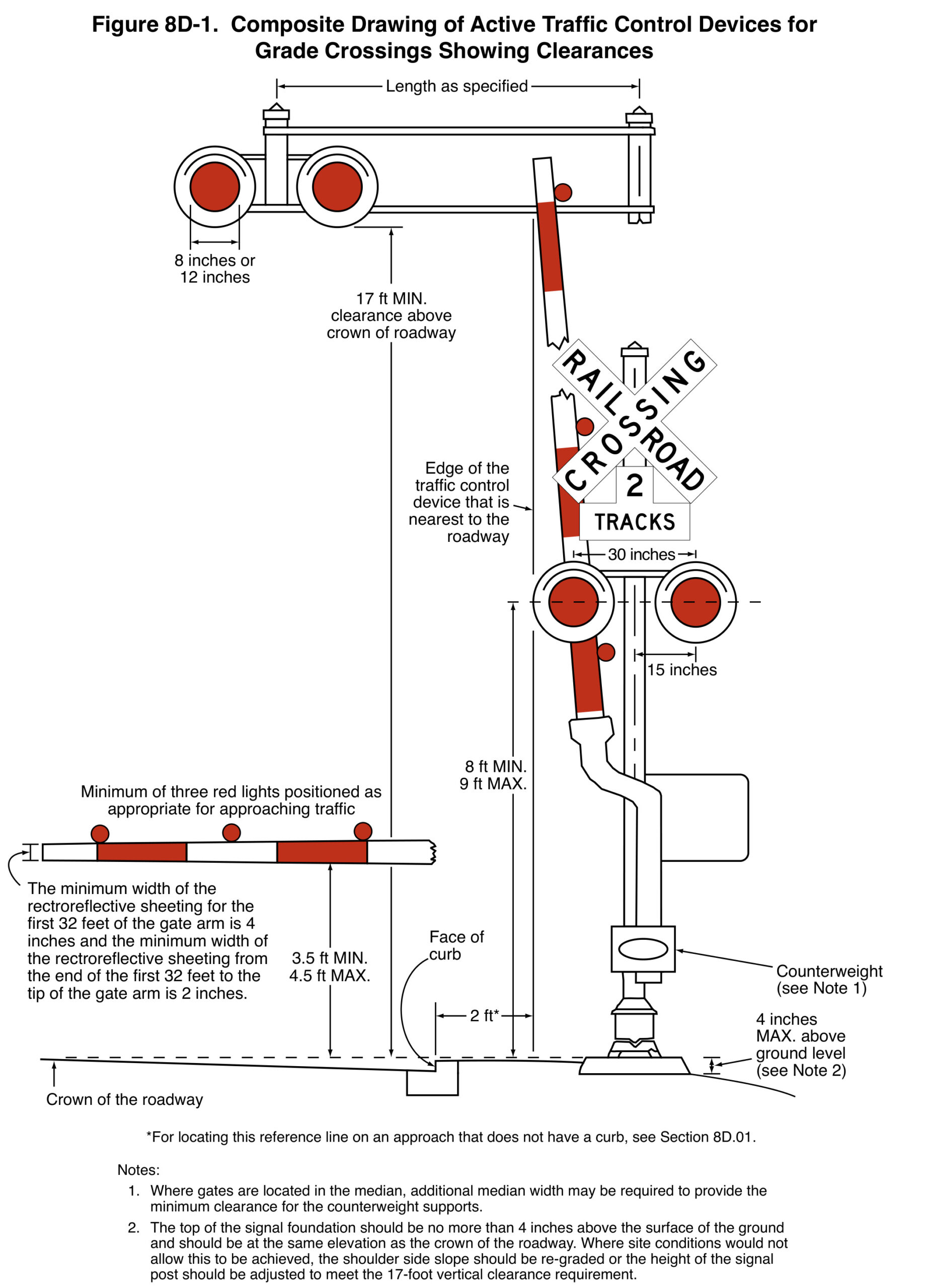
FHWA, MUTCD 11th Edition with Revision 1 (December 2025), Figure 8D-1, printed p. 1017 / PDF p. 1058. Original figure and provisions. Select the image to read the full-resolution notes.
Read the assembly and its reference points
Figure 8D-1 combines post-mounted flashing lights, an overhead arrangement, a gate and clearance notes. It explains the installation context; it is not a module dimension drawing or a complete site design.
The nominal optical diameter, the complete housing envelope and the installed height describe different things. Confirm model dimensions, supply, connections, housing fit and project acceptance using the actual product and installation documents.
Roadway and curb clearances also use different reference points from rail clearances. Preserve the figure notes and the responsible agencies' requirements.
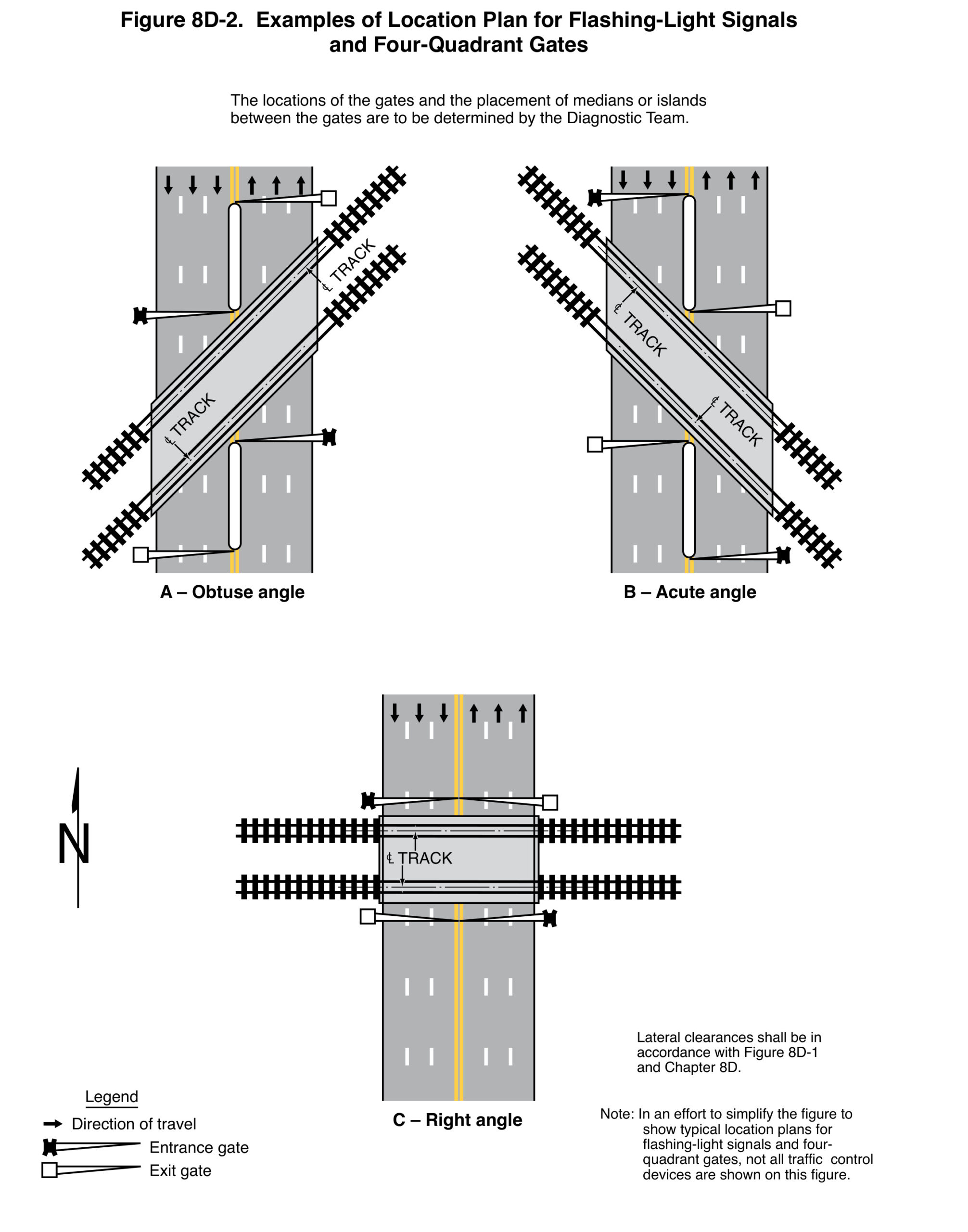
FHWA, MUTCD 11th Edition with Revision 1 (December 2025), Figure 8D-2, printed p. 1022 / PDF p. 1063. Original figure and provisions. Select the image to read the full-resolution notes.
Gate layout depends on the crossing geometry
Figure 8D-2 shows acute, obtuse and right-angle examples. The Diagnostic Team determines gate and median placement. Four-quadrant describes closure of entrances and exits, not a fixed count of four physical gate arms.
The figure deliberately omits other traffic-control devices. Its simplified plan cannot establish a complete warning installation, train-detection arrangement, power design or preemption sequence.
Does a nominal 12-inch size establish the complete signal-head dimensions?
No. Check the optical module, complete housing, background, mounting and connections separately. Use the actual drawings rather than scaling a photograph or the MUTCD illustration.
Does selecting a module verify the complete crossing system?
No. Gates, detection, warning operation, standby power and any highway-signal interconnection require their own coordinated review and acceptance.
Can the location plan be used as a construction detail?
No. It is a simplified example with omitted devices and stated qualifications. The accepted site design and complete applicable provisions govern the installation.
What should accompany a replacement inquiry?
Identify the existing assembly and module, proposed configuration, supply, connections, mechanical interface and applicable project requirements. Include photographs for context and drawings for fit; do not infer compatibility from nominal diameter alone.
Need a quote or more details about our collaboration? At LEOTEK, we’re ready to provide you with professional advice and friendly service, bringing you closer to a smart and sustainable future.