


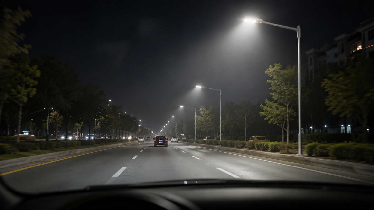
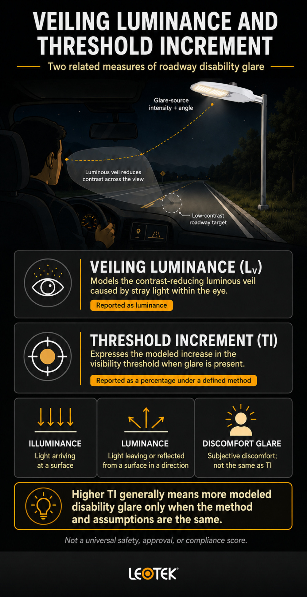
Veiling luminance describes the contrast-reducing luminous veil caused by stray light in the eye, while threshold increment expresses how much more contrast is needed to see a target when glare is present. Together, veiling luminance and threshold increment help engineers evaluate roadway disability glare, but the results are meaningful only when the governing method and its assumptions are identified.
This distinction matters during the planning and review of roadway and outdoor lighting applications. A roadway can satisfy one photometric criterion and still require review under other applicable criteria. Glare analysis therefore belongs in a complete lighting evaluation rather than serving as a stand-alone declaration of visibility, safety, or compliance.
Key takeaways
- Veiling luminance models the contrast-reducing effect of stray light within the eye.
- Threshold increment, commonly abbreviated TI, expresses the modeled increase in the visibility threshold as a percentage.
- Higher values generally indicate more disability glare only when results use the same method and assumptions.
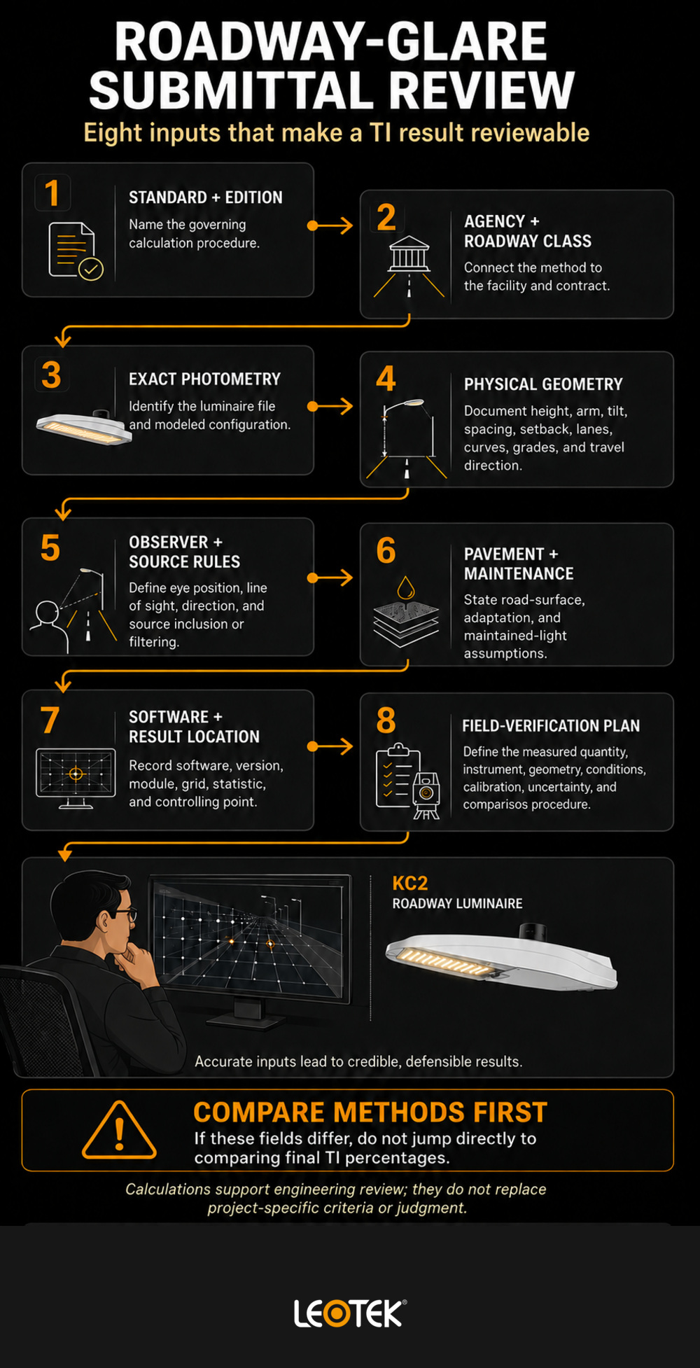
- A useful submittal identifies the standard, edition, software, observer geometry, road model, photometric data, and calculation settings.
What disability glare means on a roadway
Disability glare is a visibility effect. Light from a bright source enters the eye and scatters within its optical media. That scattered light is superimposed on the retinal image, reducing retinal contrast between a target and its background.
The target does not have to disappear completely for the effect to matter. A low-contrast object against the pavement may become harder to distinguish even when the road appears well lighted. This is why a visual impression such as “that luminaire looks bright” is not, by itself, a measurement of roadway disability glare.
Contrast loss, not simply brightness
Roadway lighting involves several different photometric quantities. Illuminance describes light arriving at a surface. Luminance describes light leaving or reflected from a surface in a particular direction, as perceived from an observer position. Luminous intensity describes light emitted in a given direction.
Veiling luminance is different from each of these, although its calculation depends on some of them. It represents a modeled luminous veil over the retinal image. The glare source’s intensity toward the observer and its angular position relative to the line of sight are particularly important because glare is directional.
This model has a physiological basis, but it should not be treated as a perfect prediction for every person. In a peer-reviewed study of 42 observers under simulated road-lighting conditions, Davoudian, Raynham, and Barrett found that veiling luminance significantly affected target-detection performance, while the observed effect was lower than expected from contrast loss alone. That result supports careful use of the metric rather than a claim that one calculated value fully represents every driver’s experience.
Disability glare versus discomfort glare
The two terms describe different effects and can occur together. The CIE addresses discomfort glare in road and vehicle lighting separately from the disability-glare calculations discussed here.
| Aspect | Disability glare | Discomfort glare |
|---|---|---|
| Primary concern | Reduced visibility or contrast | Subjective discomfort or annoyance |
| Typical evaluation | A calculated visibility-related metric, such as veiling luminance or TI under a defined method | A method intended to evaluate discomfort in the applicable setting |
| Practical question | Can the observer distinguish a target against its background? | Does the lighting cause an uncomfortable visual sensation? |
| Important limitation | A calculated result is not a universal safety determination | Comfort does not prove that visibility-related glare is controlled |
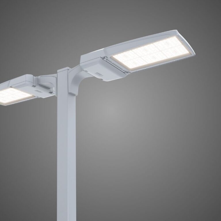
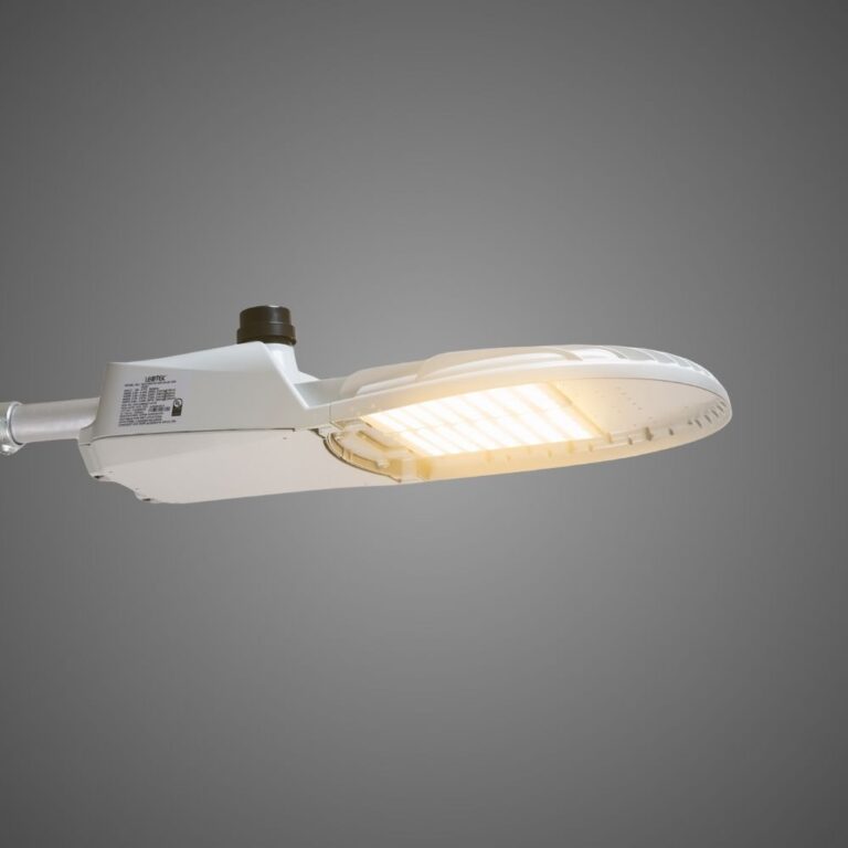
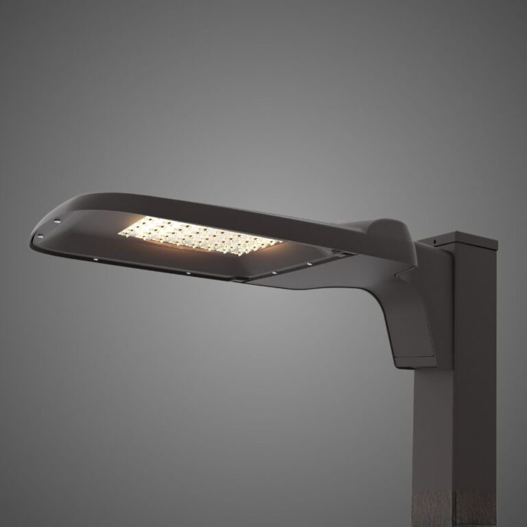
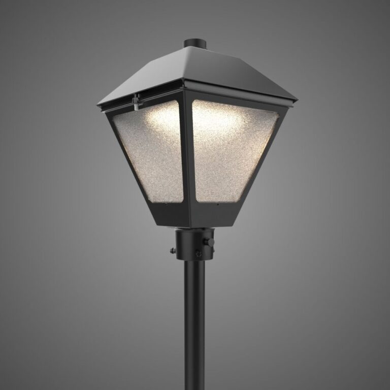
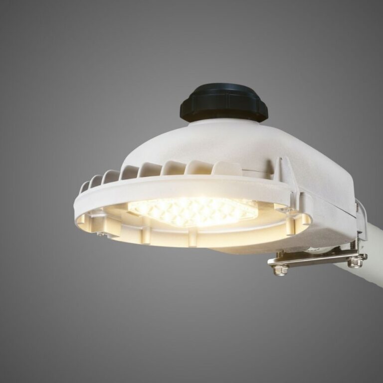
A design feature intended to reduce apparent brightness or shield a light source may be relevant to both concerns, but the terms are not interchangeable. A product description also cannot establish a project-level TI result. For example, information about low-glare optics and shielding concepts can support design exploration, but the roadway layout still requires project-specific photometric analysis.
What veiling luminance measures
Veiling luminance, often written as Lᵥ, is the modeled luminous veil produced by stray light within the eye. Its calculated value connects the luminous intensity of glare sources, their position in the observer’s field of view, and the selected observer model.
The result is expressed as luminance. Its interpretation depends on the calculation procedure, not on the number alone.
Glare-source intensity and angle
A luminaire does not emit the same intensity in every direction. Its photometric distribution determines how much light is sent toward different locations. In a glare calculation, intensity toward the observer matters along with the angle between the source and the observer’s line of sight.
That angular relationship is one reason mounting height, spacing, tilt, orientation, arm length, setback, roadway width, and travel direction can change a result. Two luminaires with similar lumen output can create different calculated glare conditions when their distributions or positions differ. Lumens alone cannot establish veiling luminance.
Calculation methods may also include or filter sources according to specified angular rules. Those rules must come from the governing standard and edition. They should not be copied from a different method simply because the software offers both options.
Observer position and line of sight
Roadway glare is evaluated from a defined viewpoint. The observer’s height, lateral position, longitudinal position, travel direction, and line of sight affect which sources enter the calculation and at what angles.
This makes directionality a core review issue. A divided roadway, an intersection approach, or opposing directions of travel may require separate evaluations under the applicable criteria. A report that shows one unexplained observer position gives the reviewer little basis for deciding whether all required cases were analyzed.
Curves and grades deserve similar attention. A simplified straight and level model may not represent the actual relationship among the driver, roadway, and luminaires. The governing agency and qualified designer must determine the appropriate method and modeling approach for the facility.
Pavement luminance and adaptation
The background against which a target is viewed affects contrast. Road-surface luminance depends on the light reaching the pavement, the pavement’s reflective characteristics, the light’s direction, and the observer’s viewing direction. It is not equivalent to horizontal illuminance.
The relevant background or adaptation quantity also matters when veiling luminance is used to derive a relative glare metric. Methods do not necessarily use identical inputs or definitions. A result should therefore document the selected pavement or adaptation assumptions, rather than reporting TI as though it were independent of the roadway model.
What threshold increment tells an engineer
Threshold increment expresses the modeled effect of disability glare as a percentage. Conceptually, it represents the additional contrast, or the increase in the relevant visibility threshold, needed to see a target with glare present compared with the condition without that glare.
Within the same method, a higher TI generally means more modeled disability glare. The comparison stops being reliable when the standard, edition, observer geometry, road model, source filtering, or other settings change.
How veiling luminance and threshold increment relate
Veiling luminance describes the luminous veil. Threshold increment relates that veil to the applicable background or adaptation condition and expresses the effect in relative terms. This makes TI convenient for comparing design alternatives under a common set of assumptions.
The relationship can be summarized without presenting a universal equation: more veiling luminance relative to the relevant road-surface or adaptation luminance generally leads to a higher threshold increment within the selected method.
That sentence is an interpretation, not a calculation instruction. Different documents use method-specific equations, inputs, observer conditions, and source-handling rules. The calculation must follow the exact standard and edition adopted for the project.
Why TI is not a universal score
A TI value without its method is incomplete. It does not reveal whether the calculation used a roadway method, an obtrusive-light method, an older standard, current procedures, or customized software settings.
Edition control is especially important. The official abstract for CIE 140:2019, *Road Lighting Calculations, 2nd Edition* states that the report improved the TI calculation and corrected the previous calculation formula. Consequently, an older equation should not be presented as a timeless definition of how TI must be calculated.
The same caution applies to pass/fail limits. A universal acceptable percentage cannot be inferred without the governing standard, roadway class, agency specification, and project conditions. Passing one criterion also does not establish overall roadway safety or compliance.
An illustrative comparison
Consider two proposed layouts modeled with the same road geometry, pavement assumptions, luminaire photometric data format, observer positions, calculation method, and software settings. If Layout A produces lower veiling luminance and TI than Layout B at the controlling location, Layout A produces less modeled disability glare under that defined comparison.
This example does not assign fabricated values or declare either layout acceptable. It shows why holding inputs constant is necessary. If Layout B uses another pavement table or standard edition, the numerical difference could reflect the method rather than only the physical design.
How standards frame roadway disability glare
Standards give calculation outputs their context. For U.S. work, the applicable agency may reference an Illuminating Engineering Society practice, its own criteria, or additional contract requirements. International CIE documents may inform a project or govern work in other jurisdictions, but they should not be assumed to control every U.S. roadway.
ANSI/IES RP-8-22 in U.S. practice
The Illuminating Engineering Society identifies ANSI/IES RP-8-22 as its 2022 recommended practice for roadway and parking-facility lighting. The public catalog page shows that the document addresses vision, calculations, planning, design, maintenance, and multiple roadway applications.
The catalog description does not provide the detailed criteria or formulas needed to evaluate a project. Designers and reviewers should use the licensed document, the agency’s adopted edition, and project specifications rather than infer requirements from an abstract or a software help page.
CIE 115 and CIE 140
CIE 115:2010 addresses the selection of lighting classes for motor and pedestrian traffic using luminance- or illuminance-based concepts. CIE 140:2019 addresses road-lighting calculations and updated the treatment of TI. Their roles differ: one provides a broader class framework, while the other focuses on calculation procedures.
Neither designation should be used without its edition. Nor should a result generated under a CIE procedure be described as an IES result. Clear attribution helps procurement staff, designers, and reviewers determine whether they are comparing like with like.
Information needed before comparing methods
| Report field | Why it matters |
|---|---|
| Governing standard and edition | Identifies the calculation procedure and criteria basis |
| Agency specification or roadway class | Connects the calculation to the facility and contract |
| Reported metric | Distinguishes TI, veiling luminance, a veiling-luminance ratio, and other outputs |
| Observer geometry | Defines the viewpoint and direction used for the calculation |
| Source inclusion or filtering | Shows which luminaires contribute under the selected method |
| Road-surface and adaptation assumptions | Defines the relevant background condition |
| Software name and version | Supports reproducibility and review of implementation |
| Calculation grid and result location | Shows where the controlling result occurs |
If these fields differ, compare the methods first. Do not jump directly to comparing the final percentages.
How to review a roadway-glare calculation and photometric submittal
A review should begin before modeling. The agency or project team needs to identify the governing criteria, roadway classification, travel directions, design condition, standard edition, and required outputs. That foundation prevents a technically polished report from answering the wrong question.
Confirm the physical and photometric inputs
Submittal review checklist: Request enough information to reproduce and evaluate the model:
- The luminaire photometric file and exact modeled configuration.
- Mounting height, arm length, tilt, orientation, spacing, and setback.
- Road geometry, lane arrangement, curves, grades, and directions of travel.
- Pavement reflectance or classification assumptions.
- Maintained-light assumptions when required by the governing criteria.
- Observer position, eye height, line of sight, and source inclusion or filtering.
- Software name, version, calculation module, standard, and edition.
- Calculation grid, reported maximum or other required statistic, and its location.
For alternative layouts, require a common input set unless a difference is intentional and clearly identified. A changed luminaire distribution may be the design variable; a silently changed pavement assumption should not be.
Check the result in context
Veiling luminance and TI should be reviewed alongside all other applicable lighting criteria. Average pavement luminance, illuminance, uniformity, and glare metrics answer different questions. One cannot be substituted for another simply because it is easier to calculate or produces a favorable result.
The reviewer should also look beyond a summary table. A calculation grid can show where the controlling condition occurs, whether it aligns with a particular luminaire or approach, and whether all required directions were considered. The report should explain exclusions, custom settings, and deviations from default procedures.
Treat field verification as a separate plan
Design calculations predict performance from photometric data and modeled conditions. Field measurements observe an installed system under actual conditions. The two can inform each other, but they are not automatically equivalent.
The official description of CIE 194:2011 emphasizes instrument characteristics, measurement conditions, measurable approximations, data processing, and uncertainty for road- and tunnel-lighting measurements. A field plan should likewise define the quantity being measured, instrument suitability, geometry, environmental conditions, calibration, uncertainty, and comparison procedure. The abstract alone does not supply a complete TI measurement protocol.
Avoid common interpretation mistakes
- Do not treat lumens, illuminance, luminance, uniformity, veiling luminance, and TI as interchangeable.
- Do not call a bright-looking luminaire proof of disability glare without a defined assessment.
- Do not assume a “low-glare” product label proves a project-level result.
- Do not compare outputs from different standards or editions as if they used the same method.
- Do not report only an average when the governing procedure requires a maximum or another specified result.
- Do not treat one glare metric as a universal safety, approval, or compliance determination.
Frequently asked questions
Is higher threshold increment better or worse?
Within the same calculation method and assumptions, higher threshold increment represents more modeled disability glare. Values produced under different standards, editions, observer setups, or road models should not be compared directly.
Can a roadway meet illuminance targets and still have disability-glare concerns?
Yes. Illuminance and disability-glare metrics describe different aspects of the lighting environment. A project must be evaluated against each applicable criterion rather than using illuminance as a substitute for glare analysis.
Is threshold increment the same as a veiling-luminance ratio?
No. They are related ways of evaluating disability glare, but the reported metrics and calculations differ. The report should name the metric and the exact method instead of using the terms interchangeably.
Does threshold increment measure discomfort glare?
No. TI is a disability-glare metric related to visibility and contrast. Discomfort glare concerns an uncomfortable visual sensation. The effects can coexist, but controlling one does not prove that the other is controlled.
Can TI be verified in the field?
Field assessment requires a defined method, suitable instruments, controlled geometry and conditions, and an uncertainty analysis. It should not be assumed to reproduce a design calculation unless the comparison procedure explicitly establishes that relationship.
Why can two lighting programs report different threshold-increment results?
Programs, or different settings in the same program, may implement different standards, editions, observer geometry, source filtering, or road and adaptation assumptions. Compare results only after the calculation method, inputs, software version, and settings are aligned and documented.
What should an agency request in a photometric submittal with a TI result?
At minimum, request the governing standard and edition, agency criteria, software and version, photometric file, roadway and pavement model, observer setup, source-filtering settings, calculation grid, reported statistic, and result location. Require qualified engineering review for the actual project and jurisdiction.
Use glare metrics as part of engineering review
Veiling luminance and threshold increment are most useful when they make a design review more transparent. They do not replace engineering judgment; they give the project team a structured way to examine how glare may reduce roadway contrast under stated conditions.
Teams preparing a defined evaluation can use LEOTEK’s technical resources and documents to locate relevant product materials, while verifying the exact model, document date, and revision needed for the project.
References
- Davoudian, N., Raynham, P., and Barrett, E. “Disability Glare: A Study in Simulated Road Lighting Conditions,” *Lighting Research & Technology* 46(6), 695–705. Accessed July 17, 2026.
- International Commission on Illumination (CIE). CIE 243:2021, *Discomfort Glare in Road Lighting and Vehicle Lighting*. Accessed July 17, 2026.
- International Commission on Illumination (CIE). CIE 140:2019, Road Lighting Calculations, 2nd Edition. Accessed July 17, 2026.
- Illuminating Engineering Society (IES). ANSI/IES RP-8-22, *Recommended Practice: Lighting Roadway and Parking Facilities*. Accessed July 17, 2026.
- International Commission on Illumination (CIE). CIE 115:2010, *Lighting of Roads for Motor and Pedestrian Traffic*, 2nd Edition. Accessed July 17, 2026.
- International Commission on Illumination (CIE). CIE 194:2011, *On Site Measurement of the Photometric Properties of Road and Tunnel Lighting*. Accessed July 17, 2026.
- LEOTEK. “Outdoor Lighting”. Accessed July 17, 2026.
- LEOTEK. “ComfortView | Human Centric Lighting”. Accessed July 17, 2026.
- LEOTEK. “Resources & Documents”. Accessed July 17, 2026.