


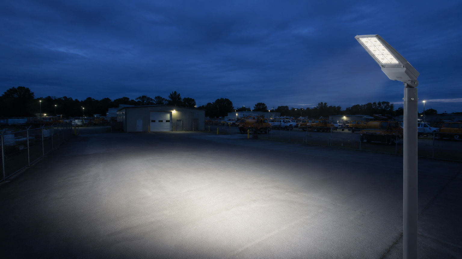
A floodlighting beam angle is only one input: start with the task area, then test the actual luminaire photometry against mounting height, setback, and aiming direction. Beam angle alone cannot confirm coverage, glare control, structural suitability, or compliance with a local requirement.
For city and transportation-agency projects, the practical question is not “What beam angle should we use?” in isolation. It is: “How can the proposed distribution place light on the required surfaces while limiting unwanted light outside them?” That question needs a documented design review, not a generic mounting-angle rule.
Key takeaways
- A beam angle describes part of a luminaire’s intensity distribution. It is not a universal recommendation for the fixture’s tilt or mounting angle.
- The same beam angle can produce different results when mounting height, setback, orientation, obstructions, or surface conditions change.
- Review the complete photometric data with the target geometry before selecting a distribution or fixing an aim point.
- Check spill, direct glare, shadows, uniformity, adjustment access, and project-specific requirements together.
Start with the lighting task, not a fixture label
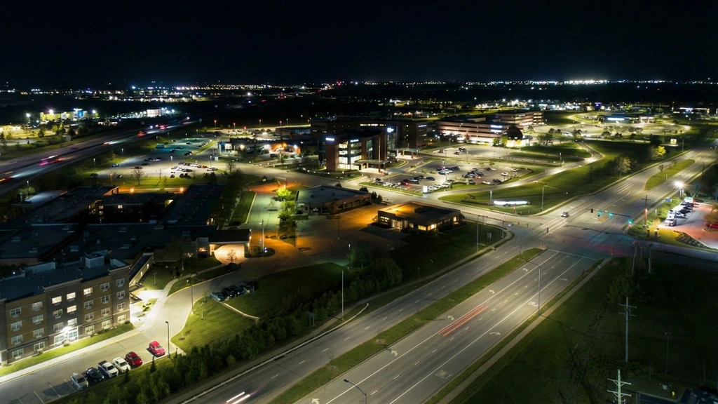
Floodlighting often serves a defined outdoor task: an access road, loading area, transit facility, parking area, public plaza, maintenance yard, or the perimeter around an infrastructure asset. Each setting has different target surfaces, viewing directions, operating periods, and boundaries. A useful beam-control discussion begins by documenting those conditions rather than starting with a fixture label or a preferred number of degrees.
Define the area that requires light. Record its dimensions, surface elevations, operating schedule, and the viewpoints from which people will see the luminaire. A plan for a vehicle approach may need a different review from one for a pedestrian connection or a work area. The project team should also identify adjacent properties, windows, travel lanes, camera locations, reflective surfaces, and habitat-sensitive areas where relevant.
Then define what should not receive unnecessary light. This can include a property boundary, an upper-story window, an approaching driver’s view, an adjacent lane, or the sky above the installation. That exercise makes beam control concrete: the designer is balancing a defined task area against defined exclusion zones.
For broader category orientation, readers can review LEOTEK’s outdoor lighting applications. It is an application pathway, not a substitute for model-specific photometry or a site design.
Write the design questions before choosing a distribution
Good project questions are specific enough to test:
Which horizontal and vertical surfaces need illumination?
- Where may the luminaire be located, and which directions are constrained?
- Which observer locations require a glare and spill review?
- What mounting, maintenance, structural, electrical, environmental, and local requirements apply?
- What drawings, calculations, and field checks will demonstrate that the approved design was installed as intended?
These questions do not determine a light level or a fixture. They create the inputs a qualified lighting professional needs to develop and verify the layout.
What a floodlighting beam angle tells you
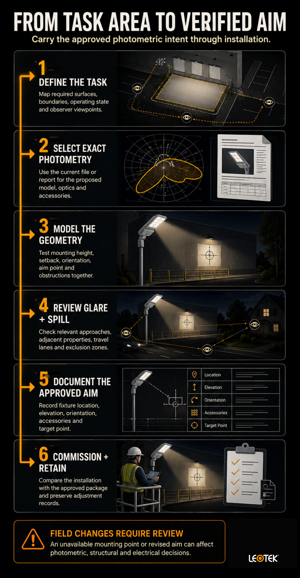
The Illuminating Engineering Society (IES) defines beam angle as the angle between the two directions where intensity is 50% of the maximum intensity, measured through the nominal beam centerline. For a distribution without rotational symmetry, the beam angle is generally reported in two planes at 90 degrees to one another.
That definition is useful because it distinguishes a photometric description from a design conclusion. Beam angle describes a portion of the intensity pattern. It does not say how far the light will reach at a particular mounting height, how sharply the light falls at the edge of a target, whether the target is evenly illuminated, or whether an observer will experience objectionable glare.
Beam angle is not mounting angle
Beam angle concerns the light distribution leaving the luminaire. Mounting angle concerns the physical orientation of the luminaire. The two interact, but they are not interchangeable.
A designer might rotate a luminaire to place its beam centerline over a target surface. That rotation does not change the photometric definition of the beam angle. Conversely, two luminaires aimed at the same point may create very different patterns because their distributions, mounting heights, and distances differ.
This is why a generic instruction to “aim every floodlight at 45 degrees” is not a reliable design method. It bypasses the geometry and photometry that determine where the light actually lands. It can also obscure the need to assess view angles, shielding, and the site’s physical constraints.
Why beam spread is only a starting point
A simple geometric footprint can be a useful early illustration, but it is not a photometric calculation. Actual results depend on the full intensity distribution, mounting height, setback, tilt, orientation, obstructions, surface reflectance, and the selected configuration. The complete IES file or photometric report shows information that a single beam-angle value cannot.
Ask for the exact model configuration, the current photometric file or report, mounting information, and any relevant aiming accessories. Do not infer output, optical behavior, ingress protection, controls, warranty, listing, or compliance from a product-family page. Those details are configuration-specific and should be checked in current documents.
Choose beam control from geometry and photometry
The most reliable sequence is to map the target first, then compare the luminaire distribution to the geometry. Begin with the target plane or planes, the possible mounting points, and the physical obstructions. Next, model where the beam centerline and edges will fall. Finally, assess light levels and viewing conditions in a calculation tool or other qualified design process using the actual photometry.
Match the distribution to the target shape and distance
A more concentrated distribution may be considered when a target is relatively distant or constrained. A broader distribution may be considered when a target is closer or wider. Neither description establishes that the result will be adequate, uniform, or low-glare. It simply identifies a distribution concept to test.
Target shape matters as much as target size. A long, narrow lane, a broad rectangular apron, and a vertical facade present different geometry. Where the distribution is asymmetric, the orientation of its major and minor planes also matters. The design should show that orientation rather than leaving it to a field installer to guess.
IES light-distribution types answer a different question from floodlighting beam angle. Those labels should not be treated as interchangeable. Likewise, total lumens cannot be converted directly into illuminance at the target without the geometry and distribution.
Model mounting height, setback, and aiming together
Mounting height and setback affect both reach and the observer’s view of the luminaire. Raising a fixture, moving it away from a target, or changing its tilt can change coverage, shadows, and spill. Test these variables together rather than selecting one in isolation.
A practical drawing package can show:
- fixture location and mounting elevation;
- target boundaries and calculation grids;
- beam centerline and proposed aim point;
- distribution orientation for asymmetric optics;
- exclusion zones and observer viewpoints; and
- proposed shielding or accessory position, where applicable.
For an elongated target, a single aim point may not be the best concept. The qualified design review may compare several luminaire locations, distributions, or aim points. The goal is not to force every site into one geometry. It is to identify a documented arrangement that the project can evaluate and later reproduce.
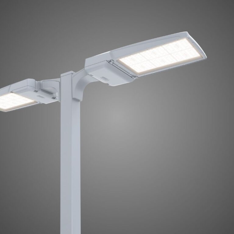
LEOTEK’s VersaTEK flood and area lights are a relevant family-level pathway for readers researching flood, site-and-area, and off-roadway applications. Before any product selection, confirm the exact model’s current photometry and documentation for the intended configuration.
Evaluate floodlight aiming for glare and spill
The joint IES and DarkSky Five Principles for Responsible Outdoor Lighting resource describes outdoor lighting as useful, targeted, low level, controlled, and warm-colored. Its targeted-lighting principle calls for shielding and careful aiming so light falls where it is needed rather than spilling beyond the intended area.
This is a sound design direction, but it is not a blanket approval for a fixture or layout. The project must still evaluate the actual distribution, observer positions, property boundaries, local rules, and site conditions. A shield can change the distribution and should be represented in the photometric review where it is part of the proposed installation.
Check the views that matter
Evaluate the layout from the locations where light can cause concern, not only from directly below the fixture. A field and calculation review can include:
- driver approaches and turning movements;
- pedestrian approaches and entrances;
- nearby travel lanes and transit stops;
- adjacent properties and upper-story windows;
- cameras, signs, and other reflective surfaces; and
- elevated or distant viewpoints that could reveal spill.
Direct glare is not resolved by a single preferred tilt. A small change in location, mounting height, aim point, distribution, shielding, or output may alter the result. Record the viewpoint and the condition being addressed so the adjustment is traceable.
Controls may be part of the operating strategy, but a control schedule should not be treated as a substitute for reviewing an improperly aimed distribution. Evaluate the intended operating state, including any dimmed condition, against the project’s approved criteria.
Select mounting locations that can be adjusted and maintained
An effective aim point is of little value if the mounting location cannot safely hold the luminaire, be accessed for adjustment, or retain its orientation in service. Consider adjustment access, potential vibration, maintenance routes, vegetation or equipment that may obstruct the light, and seasonal changes that could affect the view of the target or nearby properties.
Where adjustment is part of the approved design, mounting hardware and access provisions should support controlled adjustment and documentation. The final schedule can identify the fixture, location, height, orientation, and aim point used in the approved design. This makes later inspection or replacement more defensible than a verbal instruction such as “aim toward the lot.”
Keep structural and electrical review separate
Photometric suitability does not establish structural or electrical suitability. A mounting location still needs the applicable review of the pole, wall, structure, wind exposure, luminaire weight, wiring, overcurrent protection, grounding, access, and local requirements. Those determinations belong to qualified professionals and the authority having jurisdiction.
Effective projected area for luminaires can help readers understand one input used in fixture and pole planning, but effective projected area alone does not establish that a pole or mounting location is suitable. Treat it as background reading, not as a structural approval.
Avoid field instructions that replace project-specific electrical or structural design. If the approved layout changes because a location is unavailable, the photometric, structural, and electrical implications should be reviewed before the change is accepted.
Validate the design before and after installation
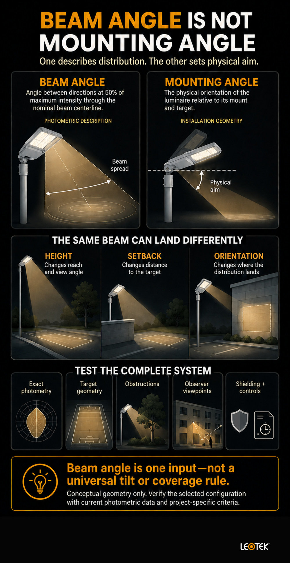
Beam control should remain traceable from submittal through commissioning. Before procurement, preserve the materials that explain what was evaluated. That record helps the owner, designer, installer, and maintenance team distinguish an approved change from an undocumented field adjustment.
Review the calculation package before procurement
For a project-specific review, retain the exact model and configuration, photometric file or report, mounting detail, aiming schedule, calculation grid, assumptions, operating state, and applicable project criteria. If a shield, visor, control setting, or mounting accessory is part of the analysis, identify it clearly.
The calculation should be read alongside the layout. Numbers without fixture locations, aiming directions, and observer considerations can hide the source of spill or glare. Conversely, a clean drawing without documented photometry does not establish expected light levels or distribution behavior.
For current specifications, guides, warranties, and other source material, consult LEOTEK technical documents for the exact model and revision. The project team should then confirm that the documents apply to the proposed configuration.
Commission and document final aiming
After installation, compare the installed locations, orientation, and accessories with the approved package. A qualified verification process can include measurements and observations against the project’s criteria, together with checks from the identified glare and spill viewpoints.
Document the final aim rather than relying on memory. Photographs, fixture identifiers, aiming directions, mounting elevations, and adjustment records can help future maintenance preserve the design intent. Commissioning does not guarantee performance under every condition, but it provides a structured opportunity to identify whether the installed arrangement matches the reviewed one.
Frequently asked questions
What is the difference between beam angle and mounting angle?
Beam angle describes part of the luminaire’s light-intensity distribution. Mounting angle describes the fixture’s physical orientation. Both affect the final result, but a beam angle does not prescribe how the fixture should be tilted.
What does beam angle mean on a floodlight photometric report?
It identifies the angle between directions at 50% of maximum intensity through the nominal beam centerline. It does not, by itself, predict site coverage or glare.
How do I choose a floodlighting beam angle for a parking or transportation facility?
Start with the task area, possible mounting locations, exclusion zones, and observer viewpoints. Then evaluate candidate distributions using the exact photometric data, mounting height, setback, and aim point. A qualified design review should confirm project-specific requirements rather than relying on a universal degree value.
Can a wider beam reduce glare?
Not necessarily. Glare depends on the distribution, brightness, orientation, mounting geometry, shielding, and the observer’s position. Compare candidate arrangements from the relevant viewpoints instead of assuming a wider or narrower beam will solve the issue.
Do I need an IES photometric file to plan floodlighting?
For a documented technical review, the exact photometric file or report is the appropriate basis for evaluating a candidate configuration. A beam-angle label alone does not show the complete distribution or establish project performance.
What should be checked after floodlights are aimed?
Check the installed fixture location, orientation, accessories, target coverage, spill boundaries, and identified observer viewpoints against the approved design and project criteria. Record any final adjustment so the maintenance team can understand the intended setting.
Use beam angle as one input, not the answer.
Floodlighting beam angle is useful when it is read as part of actual photometry and project geometry. Define the task and exclusion zones first, model mounting height, setback, orientation, and aiming together, and verify the installed result against documented criteria. That approach gives agencies and project teams a clearer basis for selecting and maintaining outdoor floodlighting without relying on unsupported rules of thumb.
References
- leotek.com, outdoor lighting applications; accessed July 29, 2026.
- ies.org, beam angle; accessed July 29, 2026.
- leotek.com, IES light-distribution types; accessed July 29, 2026.
- leotek.com, VersaTEK flood and area lights; accessed July 29, 2026.
- darksky.org, Five Principles for Responsible Outdoor Lighting; accessed July 29, 2026.
- leotek.com, Effective projected area for luminaires; accessed July 29, 2026.
- leotek.com, LEOTEK technical documents; accessed July 29, 2026.